MILPOWER SOURCE
110BA1UM, REV(B)
14
8.1.2
Option 1 Dry Contacts Interface
Table 2 shows J3 pin assignment for Option 1. In this option the server interfaces to the UPS via a
quasi - RS232 communication link
Table 2 Dry Contacts Connector J3 Pin Assignment, Option 1
PIN
DESCRIPTION
NOTES
1
Remote Shutdown Return
(1)
2
Mains Fail Relay, normally closed
(2)
3
Mains Fail Relay, normally open
(2)
4
Low Bat Relay, normally open
(3)
5
Low Bat Relay, normally closed
(3)
6
Remote Shutdown
(1)
7
Mains Fail Relay, center pole
(2)
8
Low Bat Relay, center pole
(3)
9
N.C.
Notes to Table 2:
1. Connecting 5 to 12Vdc ( + to pin 6, - to pin 1) causes the UPS to shutdown if in Battery Mode
(latched).
2. If AC input is good, pin 7 is shorted to pin 2 and pin 3 is open.
If AC input is bad, pin 7 is shorted to pin 3 and pin 2 is open.
3.
If battery voltage is good, Pin 8 is shorted to pin 5 and pin 4 is open.
If battery voltage is bad, Pin 8 is shorted to pin 4 and pin 5 is open
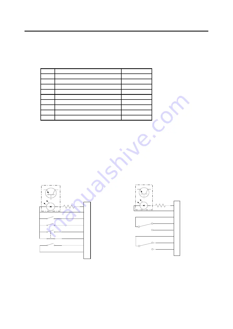
Fig 8 shows the dry contacts interface circuits for Option 1.
1K
6 REMOTE S.D. (+)
J3
7 MAINS FAIL CTR
3 MAINS FAIL N.O.
2 MAINS FAIL N.C.
1 RTN RMT S.D.
8 LOW BAT CTR
4 LOW BAT N.O.
5 LOW BAT N.C.
Figure 8 - Dry Contacts - Option 1
1K
3 REMOTE S.D (+)
J3
7 BAT V LOW
9 BAT OPER
8 UPS ON
5 SYSTEM GND
4 NOT BAT OPER
1 FLT DET HI
2 FLT DET LO
Figure 7 - Dry Contacts - Option 0


