background image

Biological hazards

BIOLOGICAL HAZARD

Contamination or infection may lead to death or serious injury, depending on the material used.

Biological material

All biological material must be considered potentially infectious.

• Wear personal protective equipment (such as gloves, safety glasses, etc.) as indicated in the safety data sheet

for the particular substance.

• If hazardous or potentially infectious material has been spilled or leaked from the system, decontaminate the

affected area.

• Operate the instrument in a biological safety cabinet suitable for the used specimen if hazardous or

potentially infectious materials are processed.

• Take care when handling samples and reagents.

• Provide sufficient lighting and workspace.

Waste

All liquid and solid waste must be considered hazardous.

• Follow local regulations regarding waste disposal.

Equipment damage

Defective or inadequate equipment can cause a biological hazard. Some decontamination methods may

damage the instrument.

• If parts of the instrument are damaged, unplug and do not use the instrument until damaged parts are

replaced. Contact Miltenyi Biotec Technical Support, if necessary.

• Follow the instructions in the datasheet for each consumable.

• Use only 70% ethanol or isopropyl alcohol for disinfection.

Chemical hazards

CHEMICAL HAZARD

Substances and reagents can be hazardous.

Hazardous substances and reagents

• All safety measures in section Biological hazards also apply to any hazardous substances and reagents that

may be present in the sample.

• Use any substances and reagents only as stated in the respective safety data sheet.

• Operate the instrument in a fume hood or with a fume extraction arm if hazardous substances and reagents

are processed.

Mechanical hazards

CRUSHING OF HANDS HAZARD

Risk of crushing or cutting.

1

IM

P

O

R

TA

N

T

SA

FE

TY

IN

FO

R

M

A

TI

O

N

12

Summary of Contents for UltraMicroscope Blaze

Page 1: ...UltraMicroscope Blaze Imaging System User manual...

Page 2: ...he preparation of this user manual However Miltenyi Biotec shall not be liable for any technical or editorial errors or omissions contained herein or for incidental or consequential damages in connect...

Page 3: ...d by Miltenyi Biotec B V Co KG Friedrich Ebert Stra e 68 51429 Bergisch Gladbach Germany Phone 49 2204 8306 0 Fax 49 2204 85197 macs miltenyibiotec de www miltenyibiotec com LaVision BioTec GmbH a Mil...

Page 4: ...s could lead to improper or incorrect usage and result in damage to the instrument Improper usage could also cause severe personal injury death unpredictable results instrument malfunction and prematu...

Page 5: ...ion 23 4 Switching on and off 25 4 1 Switching on the instrument 25 4 2 Switching off the instrument 25 4 3 Graphical user interface 25 5 Preparing the instrument 27 6 Laser alignment 29 6 1 Light she...

Page 6: ...7 3 Capturing a mosaic image 42 8 Maintenance 45 8 1 Servicing 45 8 2 Cleaning the instrument 45 8 3 Cleaning the cuvette 45 9 Technical data and specifications 47 9 1 Specifications 47 9 2 EU Declar...

Page 7: ...and prevention of accidents Ensure safe working conditions and provide for sufficient light Safe working is only possible if solely trained personnel uses the instrument The training is a permanent d...

Page 8: ...ctices or NOTICE indicates information considered important but not hazard related e g messages relating to property damage Symbols SAFETY WARNING THE DOCUMENTATION MUST BE CONSULTED IN ALL CASES WHER...

Page 9: ...nt Keep safety labels and safety markings clean and legible Inspect the safety labels and safety markings regularly and replace them if they are not legible or identifiable from a safe viewing distanc...

Page 10: ...instrument with other than the supplied cables is potentially hazardous Only use the included power cable Do not use the instrument if the power cable is damaged Only insert the plug into a grounded...

Page 11: ...and dusty environments A change in the environmental temperature may cause condensation inside the instrument Humidity condensation or dust inside the instrument can cause short circuits Use the inst...

Page 12: ...regarding waste disposal Equipment damage Defective or inadequate equipment can cause a biological hazard Some decontamination methods may damage the instrument If parts of the instrument are damaged...

Page 13: ...radiation hazards LASER RADIATION Direct exposure to laser beam may lead to eye injury Laser The instrument is equipped with a Class 3B laser product Laser BC or Class 4 laser product Supercontinuum W...

Page 14: ...h as cables lying on the floor SLIPPING HAZARD Slippery surfaces can cause injuries Ensure that the floor around the instrument is clean Servicing and transportation Servicing Improper servicing or re...

Page 15: ...EE compliance schemas By ensuring that you dispose of your unwanted electrical and electronic equipment according to the applicable WEEE and hazardous waste disposal legislation you are helping to pre...

Page 16: ...1 IMPORTANT SAFETY INFORMATION 16...

Page 17: ...their Rayleigh lengths overlapping in the entire field of view All six light sheets converge on the focal plane to illuminate all areas of the sample and minimize shadow artifacts Improved optional s...

Page 18: ...Instrument description 2 3 1 Front view Figure 2 1 Front view of the UltraMicroscope Blaze Imaging System 2 3 2 Rear view Figure 2 2 Rear view of the UltraMicroscope Blaze Imaging System 2 INTRODUCTIO...

Page 19: ...2 INTRODUCTION 19 Figure 2 3 Detail view of the I O ports and power switch 2 3 3 Equipment Figure 2 4 Jog wheel for moving the sample arm in three directions x y z and sensitivity...

Page 20: ...2 INTRODUCTION 20...

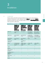
Page 21: ...eam Combiner 4 2 150 001 760 UltraMicroscope Blaze Imaging System Beam Combiner 5 5 150 001 761 light source up to 5 lasers of choice white light laser 405 nm 488 nm 561 nm 639 nm and 785 nm lasers 40...

Page 22: ...pping cap for water 150 000 495 Objective lens 12 NA 0 53 MI PLAN with dipping cap for aqueous buffers 150 000 496 Objective lens 12 NA 0 53 MI PLAN with dipping cap for organic solvents 150 000 497 D...

Page 23: ...nnel is allowed to unpack and install the instrument Please contact Miltenyi Biotec Technical Support for further information Before installation ensure that your site is properly prepared The instrum...

Page 24: ...3 INSTALLATION 24...

Page 25: ...tching off the instrument 1 Close the ImSpector software 2 Shut down Windows system 3 Switch off the UltraMicroscope Blaze Imaging System The power switch is located on the rear side of the instrument...

Page 26: ...indow Move objective to park position Moves the objective up Settings 1 window Select left light sheet Activates the selected left hand light sheet Settings 1 window Select both light sheets Activates...

Page 27: ...n Refer to chapter Switching on the instrument on page 25 2 Click Objective Lens Focus Move Objective to Park Position in the Settings 1 window Make sure the motorized turret is in the resting positio...

Page 28: ...ringe to fill the cuvette with more imaging solution up to the notch on the side 10 Press the button on the drawer to lift the cuvette The LED goes out 11 Push the drawer to close the cuvette 5 PREPAR...

Page 29: ...t sheet Figure 6 1 Screw z1 is used for aligning the left hand sheet in the z plane Screws z2 and z4 are used for aligning the three beams of each light sheet Figure 6 1 Bottom view of the UltraMicros...

Page 30: ...button on the drawer to lift the cuvette 5 Close the drawer 6 Select the excitation and emission wavelengths for the alignment tool 488 nm or 561 nm excitation under Channel Setup in the Settings 1 w...

Page 31: ...t button to move down the motorized turret The objective will automatically stop 13 If necessary adjust the Laser Transmission Control until the three beams passing the pinhole can easily be detected...

Page 32: ...ent tool with the mouse wheel You are moving in the correct direction if the beams move closer to each other The aim is to align the central beam to the pinhole located in the middle of the mask in or...

Page 33: ...um If necessary readjust the z direction 3 If a clearly recognizable single beam passes through the pinhole in the center of the mask increase the intensity of this beam by moving the alignment tool i...

Page 34: ...h the pinhole in the center of the mask of the alignment tool 5 Draw a region of interest over the three beams passing the mask in the live window and activate the intensity profile 6 Check the adjust...

Page 35: ...ble to get only one beam to pass through the pinhole refer to Adjusting the horizontal focus on page 33 6 5 Adjusting the lateral beams on the left hand side To adjust the lateral beams on the left ha...

Page 36: ...tool up and down If the intensity peaks decrease in the same way the alignment is sufficient 7 To move back the alignment tool to the reference position regardless whether the adjustment was successf...

Page 37: ...posure to laser beam may lead to eye injury Do not stare into laser beam Do not insert reflective objects or tools into the cuvette Do not manipulate the sample during measurement 1 Start the ImSpecto...

Page 38: ...and the imaging solution Optical Setup Liquid in the Settings 1 window 8 Select the excitation and emission wavelengths for your sample under Channel Setup 9 Move the slider under Laser Transmission C...

Page 39: ...ght side of the live window and draw a rectangle over a light and or a dark region by holding the left mouse button 2 Click the Adjust window level button to achieve a better contrast 3 Click the Rayl...

Page 40: ...mple until you reach the end of the z stack and click Scan Range End Take 4 Define the increment by entering it under Scan Range Stepsize 5 Check the Autosave Settings in the Measurement Wizard window...

Page 41: ...r is highlighted to set the laser power for each individual filter NOTICE Higher laser power will bleach the sample 6 Select the shortest emission wavelength and create a sharp picture 7 Optional Corr...

Page 42: ...in the Measurement Wizard window 2 Click the Mosaic tab in the xyz Table Visual XY window 3 Double click the green square representing the field of view The square will turn gray 4 Click and drag the...

Page 43: ...7 SETTING UP AN EXPERIMENT 43 5 Enter a percentage value to set an Overlap 6 To start the measurement proceed as described under Capturing an image on page 40...

Page 44: ...7 SETTING UP AN EXPERIMENT 44...

Page 45: ...table cleaning agents on a soft cloth to wipe the instrument 1 Unplug the instrument 2 To disinfect wipe accessible surfaces with 70 ethanol or isopropanol 3 If necessary wipe the instrument with a da...

Page 46: ...8 MAINTENANCE 46...

Page 47: ...l input voltage 24 V DC provided by external power supply Working conditions Temperature 15 35 C Humidity max 70 relative humidity non condensing Storage conditions Temperature 4 55 C Humidity max 70...

Page 48: ...nm Sheet optics Illumination Uni and bidirectional Number of light sheets 1 6 Thickness 4 24 m Width 1 20 mm Numerical aperture 0 0135 0 135 Focus positioning Dynamic Table 9 1 UltraMicroscope Blaze...

Page 49: ...oduct conforms to the requirements of the following directives 2006 42 EC Machinery 2014 30 EU Electromagnetic compatibility 2014 35 EU Low voltage In case of any change to the product not executed or...

Page 50: ...9 TECHNICAL DATA AND SPECIFICATIONS 50...

Page 51: ...ative or Miltenyi Biotec Technical Support at Miltenyi Biotec headquarters Miltenyi Biotec B V Co KG Friedrich Ebert Stra e 68 51429 Bergisch Gladbach Germany Phone 49 2204 8306 3803 Email technicalsu...

Page 52: ...10 TECHNICAL SUPPORT 52...

Page 53: ...notice shall include the product model and serial number if applicable and details of the warranty claim and b return the nonconforming or defective product to Miltenyi Biotec freight prepaid only aft...

Page 54: ...C HEREBY DISCLAIMS ALL OTHER WARRANTIES WHETHER EXPRESS OR IMPLIED ORAL OR WRITTEN WITH RESPECT TO THE PRODUCT INCLUDING WITHOUT LIMITATION ALL IMPLIED WARRANTIES OF MERCHANTABILITY OR FITNESS FOR ANY...

Page 55: ......

Page 56: ...cn miltenyi com France Miltenyi Biotec SAS 10 rue Mercoeur 75011 Paris France Phone 33 1 56 98 16 16 macsfr miltenyi com Hong Kong Miltenyi Biotec Hong Kong Ltd Unit 301 Lakeside 1 No 8 Science Park W...

Reviews: