Air Driven Gas Booster Compressor, 8” Drive AG Series • OM-12J
5
3. Installation
3.1 Mounting
All models will operate in any position required for system operation. However, for Oxygen Gas Boosting
applications, mount all models horizontally with mounting brackets down.
3.2 Environment
All units are protected with plating or materials of construction for installation in normal indoor or outdoor
applications. Special considerations may be advisable on some components if atmosphere is corrosive. If
ambient temperatures will drop below freezing, dryers to prevent condensation of moisture in either the
drive or gas section are advisable.
3.3 Drive System
Incoming air (or gas) piping and components must be large enough to provide sufficient flow for the cycle
rate desired. Minimum size to provide the pumping rates shown in the current catalog is 3/4” I.D. Complex
lines ov
er a considerable distance should be 1” or larger.
The standard drive inlet is a 3/4” female pipe port located in the center of the cycling valve body. As
standard, the pilot air (or gas) to the cycling system is provided through the bent tube assembly from the
1/4” NPT tap below the 3/4” NPT drive inlet port. For external remote pilot, the tube assembly is removed,
the 1/4” NPT tap is plugged, and the pilot air from an alternate source connected to the 1/8” NPT port in
the valve end cap. External pilot pressure should be equal to or exceed drive pressure. The air drive (and
air pilot if external) inlet system should always include a filter since essentially all compressors introduce a
considerable amount of contamination.
The drive requires approximately 25 psi to trigger the valve spool and pilot piston as lubricated at the
factory.
It is not necessary or desirable to use an airline lubricator.
3.3.1 MUFFLERS
For minimum noise level, these may be remotely located. If beyond 6 feet, use 3/4” I.D. pipe, tube or
hose.
3.3.2 PILOT VENT
The pilot system vents a small amount of pilot air (or gas) once per cycle from the 1/8” NPT tap in the flow
fitting end cap. This vent should operate unobstructed. It may also be piped to a remote location if the
pilot gas is hazardous. Vent purge modification with a 15 psi relief is available. Specify modification 56611
for single-ended models and 56611-2 for double-ended models.
3.4 Controls
For general usage the optional standard air controls accessory package includes a filter, an air pressure
regulator with a gauge, and a manual valve for shutoff and speed control. Pumping rates shown in the
current catalog are based on the use of a regulator with a flow capacity equivalent to 3/4” pipe size.
A number of other control options are available to suit specific applications. Among these are: Automatic
start/stop of the drive - sensing gas output and/or gas inlet pressures; high pressure safety relief
protection; cycle counting, cycle rate control, etc.
Consult current catalogs, authorized distributors or the factory.
3.5 Gas System
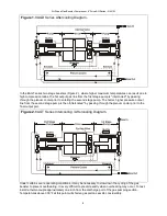
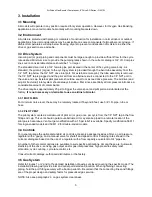
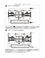
Refer to Figures 1 or 2 and to the detailed installation drawings enclosed covering the specific model. The
installation drawing will provide inlet and outlet port detail and location. When tightening connecting
piping, hold the port fitting securely with a backup wrench. Be certain that the connecting lines and fittings
are of the proper design and safety factor for pressurized gas service.
NOTE: Also see paragraph 2.3 on gas system cleanliness.
Summary of Contents for Haskel 8AGD-1
Page 15: ...8 OM 12J 15 2 3 T 2 3 1 4 25 1 8AGT 8AGD 40 1 10 1 2 3 2 3 1 5 1 10 1 80 C...
Page 16: ...8 OM 12J 16 1 8AGD 8AGT 2 8AGT 25mm 145 C...
Page 18: ...8 OM 12J 18 3 5 1 2 2 3 4 4 1 1 bar 5 5 1 CV No 242 CV O...
Page 19: ...8 OM 12J 19 IPA 50 50 5 2 5 2 1 5 2 2 3 O O 4 5 2 3 5 3 4 5...
Page 24: ...8 OM 12J 24 O 5 7 8 5 7 9 6 6 1 6 2 70 bar 6 3...
Page 26: ...8 OM 12J 26 7 7 1 7 2 7 3 1 4 bar 5 2 O O O 9 5 5 5...
Page 29: ...8 AG OM 12J 29 8AGD 8AGT 8AGD 1 2 1 1 8AGD 8AGT 2 2 1 2 2 2 8AGT...
Page 31: ...8 AG OM 12J 31 3 5 1 2 2 3 4 4 1 15 psi 5 5 1 Loctite CV Blue 242 Loctite CV O...
Page 32: ...8 AG OM 12J 32 Stoddard 50 50 5 2 5 2 1 4 5 2 2 3 O O 4 3 4 Pilot shaft end seal...
Page 38: ...8 AG OM 12J 38 B 80 500 psi 7 7 1 7 2 7 3 20 psi 5 2 O O 9 5 5 6 O 6...
Page 41: ...8 AG OM 12J 41 1 8AGD 8AGT 2 2 8AGT 1 300 F...
Page 43: ...8 AG OM 12J 43 4 1 15 PSI 5 5 1 Loctite CV 242 Loctite CV O 50 50 5 2 5 2 1...
Page 44: ...8 AG OM 12J 44 5 2 2 3 O O 4 5 2 3 5 5 2 3 1 O 2 2 1 6 30 5 2 4 5 2 1 5 2 3 3 4 5 6...
Page 48: ...8 AG OM 12J 48 5 7 3 O 5 7 4 O O 5 7 5 O 5 7 6 5 1 5 7 7 O 5 7 8 5 7 9 6 6 1 6 2 1000 PSlG 6 3...
Page 50: ...8 AG OM 12J 50 7 7 1 7 2 7 3 20 psi 5 2 O O 9 5 5 5 O 6...


