background image

2

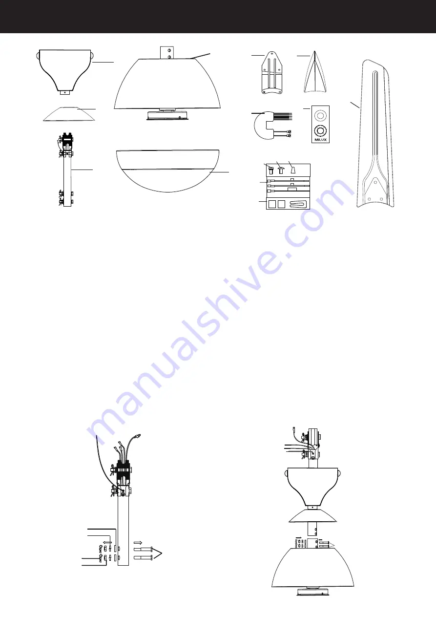
 Supplied Parts

1       Canopy             × 1

2       Yoke cover        × 1 

3       Downrod           × 1

4       Motor                 × 1

5       LED Light Kit     × 1

6       Blade holder      × 5 

7       Panel                 × 5

8       

Receiver

            × 1

9       Transmitter        × 1


Fig.3

Fig.2

Fig.1

1

Remove the parts from the both side of downrod.(Fig.2)

2

Insert downrod through canopy&yoke cover, Insert the down rod  into the motor shaft,  

Thread wires and safety cable through downrod

Aligning the down rod holes to the holes of shaft. 

Tighten the down rod to motor with the previous bolt

washer

nut and contter pin (Fig.3)

2.Downrod Installation

Bolt

Nut

Cotter pin

Spring Washer

Flat Washer

1

2

4

10

3

5

6

7

8

9

10    Blades                          × 5   

11    Blade holder screws     × 11

12    Blade screws                × 16 

13    Wire                              × 3

14    Wire connector             × 3

15    Balancing kits               × 1set

L

N

16

11

12 13

14

LIGHT

6Hr

1Hr

3Hr

LIGHT

OFF

MED

HI

LOW

Bolt

Summary of Contents for MCF- E135

Page 1: ...pecification Fan picture is for installing reference only Model MCF E135 MILUX SALES SERVICE SDN BHD Head Office No 31 Lorong Jala 14 KS10 Off Jalan Telok Gong 42000 Port Klang Selangor Malaysia Tel 1...

Page 2: ...ith the wiring rules a all pole disconnection incorporated in the fixed wiring is to be provided 11 This appliance can be used by children aged from 8 years and above and persons with reduced physical...

Page 3: ...rod into the motor shaft Thread wires and safety cable through downrod Aligning the down rod holes to the holes of shaft Tighten the down rod to motor with the previous bolt washer nut and contter pi...

Page 4: ...od aligning the pulley hole Tighten the downrod to the pulley with the previous bolt washer nut and contter pin WARNING 1 Remove the safety Cable Screw from the downrod bracket 2 Arrange and tie the S...

Page 5: ...crews bag and connect the wire to the receiver and fan 4 Connect the fan wire to the house s supply wire Diagram shows a complete assembly of the ceiling fan Fig 8 5 Finally Place the receiver in the...

Page 6: ...e it through tightening the motor screws Repeat above process to finish 5 blades installation Fig 9 Blade holder screws Blade Blade screws Panel Blade holder 2 Connect two wires from the bottom of the...

Page 7: ...light coat of shoe polish over it 5 There is no need to lubricate the fan Troubleshooting Check on the following before lodging a service report SYMPTOM PROBLEM SOLUTION Fan not moving 1 Main cables...

Page 8: ...to report a fault please contact our customer service center at MILUX SALES SERVICE SDN BHD 302263 X No 31 Lorong Jala 14 KS10 Off Jalan Telok Gong 42000 Port Klang Selangor Malaysia Toll Free 1800 88...

Reviews: