Not for
Reproduction
15
Installation
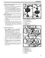
Install the Double Spindle Pulley (for Pulleys with
Hex Nut and Spring Washer)
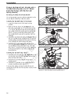
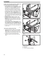
1. Install the double spindle pulley (
C,
Figure 9
) and
1/4” key (
D
) onto the spindle shaft.
2. Install the 3/4” spring washer (
B
) with the cone
facing up (
see insert,
Figure 9
). Install the 3/4-
16 hex nut (
A
) and torque to 85-90 ft. lbs (115-122
Nm). Use a 1” wrench on the flats of the blade
end of the spindle shaft to prevent the shaft from
spinning.
Install the Double Spindle Pulley (for Pulleys with
Bolt-In Tapered Hub)
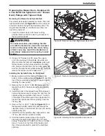
1. Remove the 1/4-20 X 1” bolts (
E
) from the tapered
hub (
F
). Install the bolts through the clearance
holes in the hub and into the new double spindle
pulley (
G
).
2. Install the pulley, hub, and 1/4” key (
D
) onto the
spindle shaft.
3. Hold the pulley at the height measured previously
and tighten the 1/4” bolts evenly. Torque the 1/4”
bolts to 8 ft. lbs. (10.9 Nm). Use a 1” wrench on the
flats of the blade end of the spindle shaft to prevent
the shaft from spinning.
Reinstall the Spindle Belt
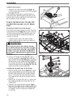
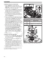
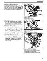
1. Refer to
Figure 10
for proper spindle belt (
A,
Figure 10
) alignment. Make sure the belt is
installed correctly on all pulleys except for the
stationary idler pulley (
B
).
The V-side of the belt should run in the pulley
grooves of the spindle pulleys (
C
) and the PTO
clutch pulley of the unit. The flat side of the belt
should contact the grooves of the stationary idler
pulley (
D
) and the adjustable idler pulley (
E
).
2. Using a 1/2” breaker bar, place the square end in
the square hole located in the end of the idler arm
(
F
).
3. Carefully rotate the idler arm either
clockwise
or
counter-clockwise
so that it lengthens the idler
spring (
G
).
4. Install the spindle belt on the stationary idler pulley
(
B
) so that the flat side of the belt contacts the
pulley groove.
F
F
G
G
B
B
A
A
C
C
Figure 10. Reinstalling the Spindle Belt
A. Spindle Belt
B. Stationary Idler Pulley
C. Spindle Pulleys
D. Stationary Idler Pulley
E. Adjustable Idler Pulley
F. Idler Arm
G. Idler Spring
C
C
C
C
D
D
E
E
Figure 9. Install Double Spindle Pulley
A. 3/4-16 Hex Nut
B. 3/4” Spring Washer
C. Double Spindle Pulley
D. 1/4” Key
E. 1/4-20 x 1” Bolts
F. Tapered Hub
G. Double Spindle Pulley (tapered bore)
A
B
C
D
E
F
G
D


