2-10
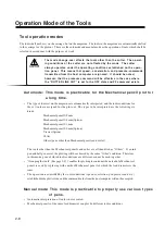
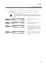
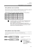
The tools conditions can be established in three different methods according to the tool operation mode and the
type of tool.For the setting method, there are two ways as shown below depending on the tools operating modes.
Find the setting method from the established mode.
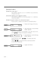
1 Auto mode
"Setting Method under Auto Mode" (See page 2-11.)
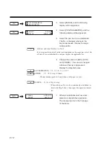
2 Manual mode
"Setting Method under Manual Mode" (See page P.2-11.)
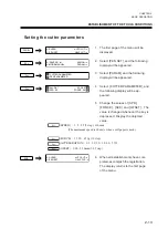
3 CUTTER PARAMETER
“Cutter parameter setting method” (See page P. 2-13)
ESTABLISHMENT OF THE TOOLS CONDITIONS
• Establish the values compatible to the selected tools and paper for the
tools conditions.
• When a cutter is used, excessively increased force of pressing may cause
to influence to the cutting quality and/or cutting service life. Apply the
suitable value.
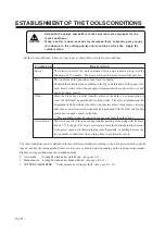
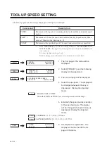
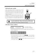
Set the tools conditions. There are four types as shown below for the tools conditions.
C o m m a n d
D e s c r i p t i o n
Speed
The relative speed of the tools and paper when a line is drawn along with the
direction of 45
°
is shown. The larger rate hear the shorter time of the plot out.
Press
The tool force of the pen and cutting force are shown.
Establish the suitable value according to the type and thickness of the paper to be
used. Increase this value if uncut paper is remained with use of a cutter, or a ball
pen do not draw clearly.
Offset
Since the blade edge is shift from the center of the holder, a compensation to
cover the shift shall be provided for cutting works. The value compensating this
disposition shall be called as the offset. An incorrec offset value causes a discrep-
ancy such as an error in size between the data produced with the CAD and the data
ploted out, rounded corners or the like.
* This condition cannot be specified for any tool other than the cutter.
Acceleration
The relative speed of the pen and paper under drawing a line along with the direc-
tion of 45
°
is shown. The larger acceleration value the shorter duration to arraive
at the preset speed with shorter plotting time. Especially, in plotting data involv-
ing a number of short lines, the working time is significantly saved.
Summary of Contents for cg-100AP
Page 16: ...xiv ...
Page 70: ...1 54 ...
Page 108: ...2 38 ...
Page 145: ...CHAPTER 4 SELF DIAGNOSIS FUNCTION 4 9 DEMONSTRATION PATTERN 1 2 Demonstration Pattern 1 ...
Page 146: ...4 10 Demonstration Pattern 2 ...
Page 173: ...CHAPTER 6 APPENDIX 6 13 Table of 82 special character codes supported ...
Page 179: ...D200310MAC 2 00 09061999 ...
Page 180: ... MIMAKI ENGINEERING CO LTD 1999 6 Printed in japan ...

