CHAPTER 3
APPLIED FUNCTIONS
3-25
A U T O M A T I C I N T E R P R E T A T I O N O F
COMMUNICATION CONDITIONS
In the following cases, the automatic interpretation may not be achieved in
some cases.
• In the case that there is an output command at the head of the data, and
queues the response from the plotter.
• In the case that an interface cable other than the assigned is used.
• In the case of ENG/ACK hand shake.
In the following cases, the interpretation may be failed in some cases.
• In the case of data for test which continuously transmit a single character,
parity checks may be failed in some cases.
• There are some cases where accurate interpretation for hand shakes can
not be obtained because it is to interpretate the possibility of hard wiring.
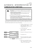
When the communication conditions of the RS-232C of your CAD are unknown, the conditions may be automati-
cally interpreted as receiving the data and registered into the assigned Nos. (#1, #2 and #3). However since the
received data would not be plotted, it is not necessary to load the paper.
1
Connect the UNIT and host computer
with the RS-232C cable.
Refer to Chapter 1 "CONNECTION
OF CABLES" (P.1-18).
2
Turn the power ON.
Refer to Chapter 1 "POWER ON/
OFF" (P.1-23)
3
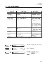
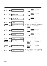
Display the sixth page of the menu.
4
Select [AUTO I/F].
5
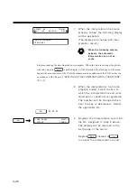
Select the interpretation, and the
following display will be appeared.
Depress
-F2+
to terminate the interpretation.
6
Data will be transmitted from the
CAD. (300 byte and over shall be
required for the data space.)
-PAGE+
<--GDP : 0.025 AUTO FEED-->
<--AUTO-I/F CONFIG-->
-F3+
JUDGMENT START
-F2+
CANSEL
Summary of Contents for cg-100AP
Page 16: ...xiv ...
Page 70: ...1 54 ...
Page 108: ...2 38 ...
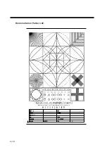
Page 145: ...CHAPTER 4 SELF DIAGNOSIS FUNCTION 4 9 DEMONSTRATION PATTERN 1 2 Demonstration Pattern 1 ...
Page 146: ...4 10 Demonstration Pattern 2 ...
Page 173: ...CHAPTER 6 APPENDIX 6 13 Table of 82 special character codes supported ...
Page 179: ...D200310MAC 2 00 09061999 ...
Page 180: ... MIMAKI ENGINEERING CO LTD 1999 6 Printed in japan ...

