background image

- 4.2 -

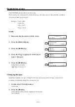
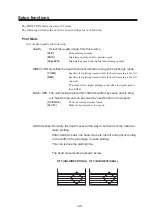
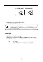
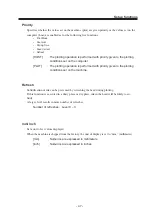
Basic operations of menus

This section describes how to change over the operation modes and how to operate the menus.

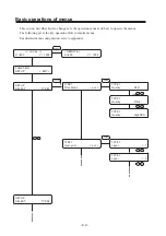
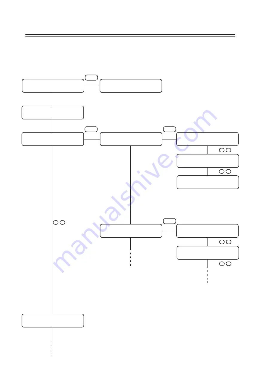
The following gives the key operation flow to invoke menus.

For detailed menu configuration, refer to Appendix.

<< LOCAL >>

X =800

Y = 1200

FUNCTION
SETUP

< ENT >

SETUP
SELECT

:  TYPE1

< REMOTE >
X =800

Y = 1200

REMOTE

TYPE1
Print Mode

< ent >

ENTER

ENTER

TYPE1
Quality

: STD

TYPE1
Quality

: FINE

TYPE1
Quality

: HighSPD

TYPE1
Over print

< ent >

ENTER

TYPE1
Layer

=  1

TYPE1
Layer

=  2

SETUP
SELECT

:  TYPE2

^

  ,  v

^

  ,  v

^

  ,  v

^

  ,  v

^

  ,  v

Summary of Contents for DM3-1810S

Page 1: ...L http www mimaki co jp E mail trading mimaki co jp D201258 OPERATION MANUAL Our customer engineer or the dealers install the plotter for you Be sure to setup the appropriate air moving system as the specified ink used of this plotter contains noxious agent When using the maintenance cleaning the ink be sure to wear the supplied goggle and glove ...

Page 2: ......

Page 3: ...NT IN NO EVENT SHALL MIMAKI BE LIABLE FOR SPECIAL INCIDEN TAL OR CONSEQUENTIAL DAMAGES OR FOR LOSS OF PROFITS OF DEALER OR CUSTOMERS OF ANY PRODUCT Requests This Manual has been carefully prepared for your easy understanding how ever please do not hesitate to contact a distributor in your district if you have any inquiry Description contained in this Manual are subject to change without notice for...

Page 4: ...ous laser radiation CDRH REGULATION The Center for Devices and Radiological Health for the U S Food and Drug Administration Implement regulations for laser products The Label shown below indicates compliance with the CDRH regulations and is labeled on the product when marketed in the United States This Model is equivalent to Class I laser device according to CDRH Regulation FCC Statement USA This ...

Page 5: ...hereinafter referred to as the machine Please read and fully understand this Operation Manual before putting the machine into service It is also necessary to keep this Operation Manual on hand Make arrangements to deliver this Operation Manual to the person in charge of the operation of this machine This Operation Manual has been carefully prepared for your easy understanding how ever please do no...

Page 6: ...Use Where to install the machine 1 2 Moving the machine 1 3 Configuration and function 1 4 The Front 1 4 The Rear 1 5 Operation Panel 1 6 Capping station 1 8 Ink cartridge and Ink station 1 9 Precautions in handling the ink cartridge 1 9 The prevention of organic solvent poisoning 1 10 Ink station 1 11 Types of work that can be used 1 12 Sizes of work that can be used 1 12 Precautions in handling ...

Page 7: ...ying machine information 2 20 To replenish ink set a new ink cartridge in the ink station 2 21 Turning the power off 2 22 Turning off the blower for the absorption table 2 22 CHAPTER 3 Daily Care Routine maintenance 3 2 Precautions during cleaning 3 2 Cleaning fluid for maintenance 3 3 Maintenance for frame components 3 3 Cleaning the ink at the bottom of the slider 3 3 Cleaning the wiper and ink ...

Page 8: ...ware version INFORMATION 5 13 Specifying the plot head line Use Head 5 14 Execute the flushing and cleaning regularly Routine Control 5 15 CHAPTER 6 When Abnormal Conditions Are Encountered Abnormal conditions where no error massage appears 6 2 The machine cannot be energized 6 2 The machine cannot perform plotting 6 2 If image quality declines 6 3 While lines thin spots are obvious or dark stripe...

Page 9: ...ror messages are given on the LCD 6 4 Errors accompanied by warnings 6 4 Error messages 6 7 APPENDIX Basic specifications A 2 Ink specification A 4 Consumable items A 5 Location of safety labels A 6 Function flowchart A 8 ...

Page 10: ...nd high speed 4 color plotting High precision plotting and high quality images The machine is capable of plotting high quality images with a maximum resolution of 720 dpi Head height adjustable to 50mm maximum This machine can print on thick work such as board tile and siding Prints on extra wide work of 1870mm maximum Up to 1870mm wide work can be set for printing over up to a1860mm wide area Ind...

Page 11: ...stem allows no head cleaning before turning off the power Nozzle logging can be recovered by performing the cleaning function The machine automatically performs nozzle clogging preventive operation at fixed intervals How ever the main power should be left turning on The machine monitors the time period when not in use When the power is tuned on or when plot ting is started it automatically perform...

Page 12: ...on that will facilitate the use of the machine Indicates the reference page for related contents Example of pictorials within the manual The symbol indicates the case where some phenomenon that requires a CAUTION sign including DANGER and WARNING signs exists A concrete precaution precaution against an electric shock in the case of the sketch given on the left is shown in the illus tration The sym...

Page 13: ... fire when using the machine When cleaning the ink station and head be sure to wear the supplied goggle and gloves since you may get ink in your eyes If anyone drinks ink in mistake keep him or her quiet and see a doctor immediately Do not allow him or her drink vomit Then contact the Poison Control Center If you absorb a lot of vapor and feel bad immediately move to a loca tion where fresh air is...

Page 14: ... lot of clean water for at least 15 minutes In this case also wash the backside of eyelids to rinse ink away completely Then consult a doctor as soon as possible Store ink cartridges and waste ink tank in a place that is out of the reach of children If ink settles on the skin or clothes immediately wash it off with detergent or water If you get ink in your eyes immediately rinse off with water and...

Page 15: ... except for maintenance page 2 3 Safety precautions during installation Protection against dust It is strongly recommended to use the device in a room that is not dusty Set the Refresh level 2 or 3 when in bad environment page 4 7 Keep the front cover to be closed also when the machine is not engaged in plotting If not dust can accumulate on the head nozzle When leaving the workshop after the work...

Page 16: ...idge as doing so may cause damage to the print circuit board CAUTION Ink cartridges If the ink cartridge is moved from a cold place to a warm place do not use for three hours Open the ink cartridge just before installing it in the ma chine If it is opened and not installed for a long time the machine may not plot normally Make sure to store ink cartridges in a cold and dark place Be sure to thorou...

Page 17: ...ectly exposed to blowing air from an air conditioner etc or you may get spattered with the ink A place that is not horizontal Do not place the machine where the machine can not be installed on a level surface or you may not secure the stabilized print work A place that vibrates Do not install the machine where it is subject to vibration or you may not secure the stabi lized plot work A place full ...

Page 18: ... on the LCD The content of display is shown in characters in a box as shown at right Operate the machine according to the explanation of the operation procedure and the content of dis play on the LCD In this Operation Manual each setting and mes sages displayed on the LCD is enclosed in like Type1 Please Wait etc Operation keys In the text of this Operation Manual the operation keys are shown encl...

Page 19: ...e This chapter describes the daily cleaning Chapter 4 How to Set Functions This chapter describes the setting function Chapter 5 Maintenance Functions This chapter describes functions intended to correct adverse influences on picture quality and to check abnormal conditions as well as the procedure to be taken to replace a used wiper Chapter 6 When Abnormal Conditions Are Encountered This chapter ...

Page 20: ... xvi ...

Page 21: ... and function of each section of the machine as well as ink and work Table of contents Where to install the machine 1 2 Moving the machine 1 3 Configuration and function 1 4 Ink cartridge and Ink station 1 9 Types of work that can be used 1 12 MENU mode 1 13 ...

Page 22: ... and to perform plot operation Model Width Depth Height Gross weight DM3 1810S 3070 mm 2560 mm 1350 mm 650 kg or less 4600 mm 5100 mm 1000 mm or more 1000 mm or more 1000 mm or more 1000 mm or more Working environmental temperature This machine should be used at 68 95 F 20 35 C to implement a stable plot The surrounding temperature condition occur different patterns ...

Page 23: ...achine take care not to apply excessive shock to it Be sure to adjust the level feet to level the machine at the new loca tion Method of moving the machine When moving the machine it must be held up by at least eight persons as illustrated at right Locking the caster Raise the level feet of the table frame before moving the machine to a new location Lower and adjust the level feet to level the mac...

Page 24: ...Power switch It turns on off the power to the machine page 2 3 8 Operation panel This panel has the operation keys required for operating the machine and the LCD for displaying set items etc 9 Waste ink tank Waste ink gathers in this tank page 3 13 10 Blower switch A switch to turn the blower On Off page 2 4 11 Table frame It supports the main unit It is provided with casters and level foots for m...

Page 25: ... 2 Ink station Set the ink cartridges specified 3 Air filter Filter out the dust or ink mist sucked the blower page 3 10 4 Blower door Open and close while turn On Off the blower main power switch page 2 4 5 Blower main A switch to turn the blower main power On Off 1 1 2 2 3 4 5 Periodic replacement parts power switch ...

Page 26: ...ge 1 12 ENTER key Used to move to the lower level menu and establish the settings XY keys They are used to shift the carriage and the medium un der the LOCAL mode In ad dition they are used to se lect a set value page 1 7 CYCLE START key Perform copy plotting page 1 13 TEST key Prints the test pattern for checking Nozzle cogging page 2 13 CLEANING key Performs head cleaning when ink clogging occur...

Page 27: ...Moves to the next function When setting a plotting origin plotting area Shifts the carriage to the left Shifts the carriage to the right Shifts the work table away from you Moves the work table toward you When inputting a choice selected among several alternatives Selects the next value Selects the last previous value Functions of the Z keys Press the Z keys to move the head Y bar height page 2 6 ...

Page 28: ...yes The capping station consists of ink caps wipers for cleaning the heads etc Cap It covers the nozzle so as to prevent the head nozzle from drying up Wiper It is used to clean the head nozzle The wipers are consumable parts If the wiper is deformed or the work is stained replace the wiper with a new one Wiper Ink Cap Flushing Tray ...

Page 29: ...he machine after replenishment of ink The ink cartridge cannot be refilled Refilling the ink cartridge can cause a trouble Remember that MIMAKI assumes no responsibility for any damage caused by the use of the ink cartridge replenished with ink Do not touch or stain the contacts of the ink cartridge as doing so may cause damage to the print circuit board If the ink cartridge is moved from a cold p...

Page 30: ...o setup the appropriate air moving system Be sure to check periodically on the air moving system Indicate precautions of danger on the human body by organic solvent Be sure to perform the environmental measurements every six months The environmental measurements and the organic solvent density measurements performed by the working environment mea surement expert Improve the result of the environme...

Page 31: ...station supplies ink to the 2 front row of Carriage The Left ink station supplies ink to the 2 rear row of Carriage Remember these relationship when checking the heads for clogged nozzles replacing ink cartridge and replenishing inks ...

Page 32: ...ty The work have to be left in the atmosphere in which they are to be used for 30 minutes or more after unpacked Warps of work Use a flat work and a warped down work its center is arched with the plotting surface up The warped up work is an unabsorbable to the table As for a warped up work place them to a smaller board or a pallet to keep it warped down Improvement of the solvent ink fixation If t...

Page 33: ...e VIEW key brings the work to the detaching position REMOTE mode The machine plots an image from data it receives During the plotting operation press the REMOTE key to interrupt the plotting operation While the machine is in the LOCAL mode press the REMOTE key to put the machine into the REMOTE mode CYCLE START mode This mode may be used in combination with Raster Link Pro to repeat plotting using...

Page 34: ... 1 14 ...

Page 35: ...ht 2 6 Setting the work on the machine 2 7 Establishing the origin and the print area 2 9 Covering in absorption holes located off the work 2 11 Checking and solving nozzle clogging 2 12 Correcting the work feed rate 2 15 Correcting the media feed rate during plotting 2 17 Plotting an image from source data 2 18 Displaying machine information 2 20 To replenish ink set a new ink cartridge in the in...

Page 36: ...m power on to end of plotting For details on each item refer to the reference page Turn on the power on P 2 3 Check the head height P 2 6 Set the work P 2 7 Set the origin and printing area P 2 9 Plot the test pattern P 2 12 Correct the work feed rate P 2 15 Start the plotting P 2 18 ...

Page 37: ...d To avoid injuries keep your hands away from the machine while in motion To prevent from clogging nozzle normally do not turn off the power When the power is turned off for mainte nance works the nozzle clogging preventa tive function operates according to the time off 3 The machine enters the LOCAL mode Display the print area BOOT DM3 1810S V Please Wait LOCAL X 1010 Y 1860 The Local mode is not...

Page 38: ...ower switch to I 3 Press the power switch once The switch light turns on The blower turns on and ready for atmospheric absorption During the CYCLE START mode the blower automatically turns off when the plotting operation is completed and the table returns to the position which media is taken off ...

Page 39: ...ting In this case re start the machine and computer following the procedure described below STEPS 1 When opening the station cover during plot ting the message shown on the right will be displayed Stop the plotting 2 Stop the data transmission from the computer 3 Close the station cover 4 Press the ENTER key 5 The carriage will start to move The carriage will carry out a series of performance same...

Page 40: ...i als Otherwise the head will touch the fluff and affect the print quality Confirm the head height setting value press the ENTER key in the LOCAL REMOTE and CYCLE mode page 2 20 STEPS 1 The machine enters the LOCAL mode Press the REMOTE key and put the machine back into the LOCAL mode 2 Press the Z or keys to adjust the head height The ideal head height is equal to the work thickness 1 0 to 2 0mm ...

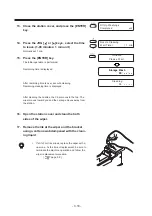
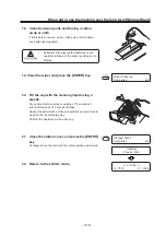
Page 41: ...warped up work is an unabsorbable to the table page 1 12 Use some tape together if the air absorption function is unable to fix some work STEPS 1 Turn on the power to the machine 2 Adjust the head height page 2 6 After adjusting return to the LOCAL mode 3 Press the VIEW key 4 Press the VIEW key or the ENTER key The table moves toward you 5 The machine revert the LOCAL mode 6 Set the work on the ma...

Page 42: ...itted to each of the screws of the work holder Do not lose them when they are removed 2 The right and left work holders may be turned upside down as needed according to the work size 3 Place the work between the work holder and the table 4 While pressing the work holder down re tighten the knob screws Right and left work holders square C shape Front and back work holders L shaped cannot be turned ...

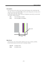
Page 43: ...Establishing the origin and the print area Initial value The origin and the print area are set as follows by default until they are changed Effective printing area Work 15mm 15mm Origin 15mm Output direction ...

Page 44: ...es as the carriage moves A cross shaped point mark appearing on the table or the work will be the display coordi nate 3 After deciding the origin press the ENTER key 4 Press the ENTER key Press the END key if the print area is to be left unchanged 5 Set the print area by pressing the XY or keys Display the new print area determined by the carriage movement 6 After deciding the print area press the...

Page 45: ... more when the holes located off the work also get cov ered on the table Cover in the holes by sheets such as papers and films as needed Use a roll support for a rolling work and a roll sheet for the absorption holes located off the work To prevent ink sucked by absorption holes cover in the absorption holes in the plotting area when setting up the plotting area located off the work ...

Page 46: ...nished test pattern shows any sign of abnormal conditions carry out the cleaning function To perform the test plot on a cut sheet medium use a medium whose size is A4 or larger with placed in landscape configuration Test Pattern 1 2 3 4 5 6 7 8 A B C D E F G H Normal Pattern Abnormal Pattern Output direction Nozzle is dirty Clogged with ink ...

Page 47: ...he XY keys or to select the head block for cleaning Refer to page 1 10 Ink station 7 Press the XY or keys to set on off of the blocks that need cleaning Do not execute the head cleaning as for 8 Press the ENTER key 9 Press the XY or keys to select the type of cleaning Normal Select this if there is any missing line Soft Select this if any line is bent Strong When printing trouble is not solved eve...

Page 48: ...ange the work or establish the new origin 13 Repeat steps 2 and 3 and check the result of the test printing Repeat STEPS 2 to 10 until normal plotting result is obtained Replace the wiper and the ink cap if inferior printing does not improve after cleaning operations page 3 4 Cleaning 00 LOCAL X 1010 Y 1860 ...

Page 49: ...ting disturbing neat plotting Correction for the work feed rate in online is available page 2 17 CORRECTING PATTERN Plot two bands Adjust the plot density so that the boundary of the two bands is plotted with an even density Setting value 100 100 Correction value is too large Correction value is too small Output direction Get between lines Overlap Second band First band ...

Page 50: ...ection value from the output pat tern When ADJUST is changed to 30 the pattern moves by about 0 1 mm Determine the correction value referencing this amount of movement 11 Press the ENTER key Register the correction value Repeat steps 8 to 11 until normal plotting result is obtained 12 Press the END key three times and the menu returns to the LOCAL mode LOCAL X 1010 Y 1860 LOCAL X 1010 Y 1860 FUNCT...

Page 51: ...e REMOTE display The altered value ceases to be in effect and returns to the previous value A new value takes effect in real time The best effect can be obtained while checking the result The unit of the correction value is the same as in Feed Correct in the LO CAL mode page 2 15 Setting value is to be Reset as follow Perform the Feed Correct Perform the Setup reset 5 Press the ENTER key Confirm t...

Page 52: ...E Quality of image priority FAST Quality of speed priority HOST setting up drawing at the computer Plotting an image from source data Starting the plotting operation The following describes the method of plotting For various function settings necessary for plotting refer to CHAPTER4 How to Set Functions STEPS 1 The machine enters the LOCAL mode 2 Press the REMOTE key The machine enters the REMOTE ...

Page 53: ... plotting operation To interrupt the plotting operation stop the carriage and erase the receive data from the machine STEPS 1 Press the REMOTE key to stop the plotting operation 2 If data is being transmitted from the computer to the machine stop the data transmission 3 Press the DATA CLEAR key The data that has been received is erased 4 Press the DATA CLEAR key or ENTER key The machine enters the...

Page 54: ...Press the ENTER key to display the ink type 6 Press the ENTER key to display the firmware version and command 7 The ENTER key displays setting status The key displays the in use setup contents 8 The ENTER key displays error information guidance The key displays current warning 9 Press the END key the machine returns to the REMOTE or CYCLE mode Return to the REMOTE mode or CYCLE mode automatically ...

Page 55: ...When INKnearEND appears the local mode is resumed and the operation stopped each time plotting of a single data is completed Proceed with Step 2 at the end of the plotting operation Proceed to Step 2 at the end of the plotting operation When INKEND appears plotting cannot be continued 2 Install a new ink cartridge Pull out the ink cartridge of the indicated number and then set a new ink cartridge ...

Page 56: ... the power of the blower is turned off To prevent from pressing the switch the parts of power switch is covered on Remove the cover when the power is tuned off Make sure that the head in the capping station If the power is turned off while the machine is engaged in plotting the head may fail to be retracted in the capping station If the head is left without capped for an extended period of time th...

Page 57: ...aning the wiper and ink caps 3 4 Cleaning the nozzle Nozzle Cleaning 3 7 Cleaning or replacing the mist filter 3 10 Replacing the flushing tray ink absorber 3 11 When the waste ink tank becomes full 3 13 Ink discharge way cleaning Drain Wash 3 14 When not in use the machine over the long term Storage Wash 3 16 ...

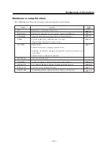
Page 58: ...ching the power cable If not unexpected troubles can arise Keep to the time limit 1 hour as power off If the power is turned on for more than 1 hour the nozzle clogging preventative function does not work In addition if the power is turned off for more than 5 days the ink flushing does not work either Do not wipe the nozzles wiper or cap of the head with water of alcohol as doing so may cause nozz...

Page 59: ...les and cause poor ink delivery Cleaning Tools Cleaning liquid for maintenance Cotton swabs Pipette Goggle Gloves Routine maintenance Cleaning fluid for maintenance Use a cleaning fluid for maintenance corresponding to the ink used ES3 ink Cleaning fluid for maintenance MS2 ES3 MS kit SPC 0369 SS1 ink Cleaning fluid for maintenance RS SPC 0336 Maintenance for frame components If the frame componen...

Page 60: ... as to keep the machine in good operation condition When cleaning the machine be sure to wear the supplied goggle and gloves since you may get ink in your eyes Remove dust from the wiper before starting head cleaning A dusty wiper may damage the head and cause defective plotting Clean the two wipers at a time Do not move the carriage out of the capping station by hand Use the appropriate operation...

Page 61: ... using a cotton swab dampened with cleaning liquid If dirt of curl is serious replace the wiper with a new one At the time of replacement be sure to terminate the plotter operation and follow the wiper replacement procedure page 5 9 8 Clean the wiper guide shaft using a cotton swab or cloth If dirt is hard to remove use a cotton swab of cloth damp ened with the cleaning liquid Extremely dirty wipe...

Page 62: ...ed to the rubber of the cap using cotton swab 10 The station cover is closed then press EN TER key Execute the initial operation 11 The machine enters the LOCAL mode Initialize Please Wait LOCAL X 1010 Y 1860 Carriage Out Completed ent ...

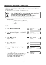
Page 63: ...head even Execute the Ink Filling function P 5 11 if the inks are mixed Operate it in the head only with the nozzle clogging Cleaning Tools Cleaning liquid for maintenance Cotton swabs Goggle Gloves STEPS 1 Press the FUNCTION key in the LOCAL mode 2 Press the XY or keys to select MAINTE NANCE 3 Press the ENTER key Station is displayed 4 Press the XY or keys to select Nozzle Clean 5 Press the ENTER...

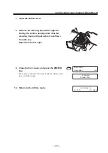
Page 64: ...llow the wiper replacement procedure page 5 9 7 Clean the wiper guide shaft using a cotton swab or cloth If dirt is hard to remove use a cotton swab of cloth damp ened with the cleaning liquid Extremely dirty wiper guide shaft may cause operational failure of the wiper resulting in error display 8 Clean the wiper and press the ENTER key 9 Fill the cap with the cleaning liquid using a pipette 10 Cl...

Page 65: ...min 12 Press the ENTER key The initial operation is performed Remaining time is displayed After remaining time is over execute cleaning It displays the remaining cleaning time 13 Cleaning is completed the menu returns the LOCAL mode Initialize Please Wait LOCAL X 1010 Y 1860 Cleaning 00 Waiting 00 Nozzle Cleaning Wait Timer 1 min ...

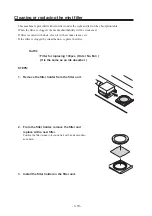
Page 66: ...sts clean it with vacuum cleaner etc If the filter is clogged by ink adhesion replace the filter Outfit Filter for replacing 100pcs Order No M 3 It is the same as an ink absorber STEPS 1 Remove the filter holder from the filter unit 2 From the filter holder remove the filter and replace with a new filter Position the filter folded in four and fix it with its all circumfer ence held 3 Install the f...

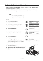
Page 67: ...is the same as a mist filter STEPS 1 Press the FUNCTION key 2 Press the XY or keys to select MAINTENANCE 3 Press the ENTER key 4 Press the XY or keys to select Station 5 Press the ENTER key 6 Press the ENTER key The table moves away from you and the Y bar moves upward The wiper moves toward you and the carriage moves away from the station 7 Open the station cover 8 Remove the F cover upward from t...

Page 68: ...t and touching the tray Otherwise it may interfere with the head nozzles 11 Place the F cover from above Place the F cover all the way down A floating cover may cause trouble 12 Close the station cover then press the EN TER key The initial operation is performed 13 Return to the LOCAL mode LOCAL X 1010 Y 1860 Ink absorber Carriage Out Completed ent Initialize Please Wait ...

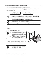
Page 69: ...until it stops dripping Dispose a long term unused waste ink regardless of its amount STEPS 1 Pull out the tank toward you When pulling out the waste ink tank hold the opening of the waste ink tank with paper and then slowly pull it out to prevent waste ink from spattering Before replacing ink put paper on the floor to prevent it from being stained with ink 2 Dump waste ink into a separate waste o...

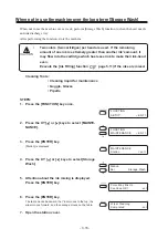
Page 70: ...ing Tools Cleaning liquid for maintenance Goggle Gloves Pipette STEPS 1 Press the FUNCTION key once 2 Press the XY or keys to select MAINTE NANCE 3 Press the ENTER key Station is displayed 4 Press the ENTER key Carriage out is displayed 5 Press the XY or keys to select Drain Wash 6 Press the ENTER key The table moves backward the Y bar moves to the top the wiper moves forward and the carriage move...

Page 71: ...n pause period drop the cleaning liquid until just before it overflows from the cap Repeat at all other caps 9 Close the front cover and press the ENTER key Dry suction continues for 30 seconds and then the machine is put in LOCAL mode 10 Return to the LOCAL mode Drain Wash Completed ent Initialize Please Wait LOCAL X 1010 Y 1860 ...

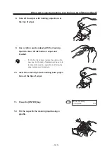
Page 72: ... function page 5 11 if the inks are mixed Cleaning Tools Cleaning liquid for maintenance Goggle Gloves Pipette STEPS 1 Press the FUNCTION key once 2 Press the XY or keys to select MAINTE NANCE 3 Press the ENTER key Station is displayed 4 Press the XY or keys to select Storage Wash 5 Attention about the ink mixing is displayed Press the ENTER key 6 Press the ENTER key The table moves backward the Y...

Page 73: ... off ink blots on wiper and bracket If dirt of curl is serious replace the wiper with a new one At the time of replacement be sure to terminate the machine operation and follow the wiper replacement procedure 10 Insert the clean wiper with holding both projec tions at the tips of wiper 11 Press the ENTER key 12 Fill the cap with the cleaning liquid using a pipette Wiper Cleaning Completed ent ...

Page 74: ... to the top The wiper moves toward you and the carriage moves away from the station 16 Open the station cover and clean the both sides of the wiper 17 Remove the ink at the wiper and the bracket using a cotton swab dampened with the clean ing liquid If dirt of curl is serious replace the wiper with a new one At the time of replacement be sure to terminate the machine operation and follow the wiper...

Page 75: ...s the ENTER key 20 Fill the cap with the cleaning liquid using a pipette Dry suction starts in cycles consisting of 10 seconds of suction followed by 10 seconds of pause Repeat the performance of the air aspiration several times to clean up the ink discharge way Perform the operation for the each cap 21 Close the station cover and press the ENTER key Carriage returns the station to the initial ope...

Page 76: ... 3 20 ...

Page 77: ...APTER 4 How to Set Functions This chapter describes how to set up the machine Table of contents Basic operations of menus 4 2 Registering a type 4 4 Setup functions 4 5 Change the display language DISPLAY 4 10 ...

Page 78: ...e key operation flow to invoke menus For detailed menu configuration refer to Appendix LOCAL X 800 Y 1200 FUNCTION SETUP ENT SETUP SELECT TYPE1 REMOTE X 800 Y 1200 REMOTE TYPE1 Print Mode ent ENTER ENTER TYPE1 Quality STD TYPE1 Quality FINE TYPE1 Quality HighSPD TYPE1 Over print ent ENTER TYPE1 Layer 1 TYPE1 Layer 2 SETUP SELECT TYPE2 v v v v v ...

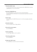
Page 79: ...ivided into two the setup function and maintenance function Select either function 3 Select a type There are four types The FUNCTION mode can be set for each type depending on the media type used 4 Select the Function Select the function pressing the XY or keys 5 Enter the Function selected Press the ENTER key 6 Select a parameter Press the XY or keys to select a parameter 7 Enter the specified va...

Page 80: ...ress the XY or keys to select any of types 1 through 4 5 Press the ENTER key Setting Plotting Conditions page 4 5 through 4 7 Changing the type If plotting conditions for types 1 through 4 have already been registered settings can be selected according to the plotting simply by selecting the type 1 Perform steps 1 through 5 above Select a type 2 Press the END key Plotting with the plotting conditi...

Page 81: ...ng to the left BI D Specifies that plotting is made while the head is moving to the left and right This mode allows higher plotting speed with a lower plot quality than UNI D Return SPD The unidirectional plot within 1000mm width may cause nozzle drop out Nozzle drop out can be solved by head s return at low speed NORMAL The head returns at normal speed SLOW Make the head return at low speed LOGIC...

Page 82: ...ting Overprinting will cause the media to expand contact by ink moisture produc ing wavy finished surface DRYING TIME It sets the function for drying ink The drying time is the wait time by scanning Specify the time to be established in accordance with the plotting resolution on a plotting and the type of work to be used Time 0 0 9 9 sec Sets the time of temporary stop by scanning of the head ...

Page 83: ... operation is performed with priority given to the plotting conditions set on the machine Refresh Solidification of ink can be prevented by refreshing the head during plotting If this function is executed in a dusty place or dry place ink in the head will be likely to so lidify A larger level results in more number of refreshes Number of refreshes Level 0 3 mm inch Set a unit of set values display...

Page 84: ... g unwanted stripes may appear on the image to correct the work feed rate Offset 100 100 Auto Clean The head is cleaned automatically Perform cleaning for each print to prevent plotting failures ON The head is cleaned automatically OFF The head is not cleaned automatically ...

Page 85: ...the origin The plot able width becomes smaller Therefore when plotting is made all the way to both ends of the media turn this function off ON The color pattern is plotted OFF The color pattern is not plotted Setup Reset This function resets the current plotting conditions to the factory set plotting conditions Execute this function for each of the types of set plotting conditions ENTER All setup ...

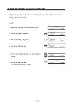
Page 86: ...to ENGLISH STEPS 1 Make sure that the mode is LOCAL mode 2 Press the FUNCTION key 3 Press the XY key twice 4 Press the ENTER key 5 Press the XY or keys to select the lan guage 6 Press the ENTER key The machine enters the LOCAL mode LOCAL X 1010 Y 1860 FUNCTION SETUP ENT FUNCTION DISPLAY ENT DISPLAY JAPANESE ent DISPLAY ENGLISH ent LOCAL X 1010 Y 1860 ...

Page 87: ... of the machine 5 2 Plotting setup conditions LIST 5 4 Plotting HEX CODE DATA DUMP 5 5 When medium thickness is changed Print Adjust 5 6 Cleaning the station interior Station Carriage Out 5 8 When the message Replace Wiper is displayed Station Wiper Exchng 5 9 Fill up the ink Ink Filling 5 11 Wiper Life warning Wiper Level 5 12 Displaying the firmware version INFORMATION 5 13 Specifying the plot h...

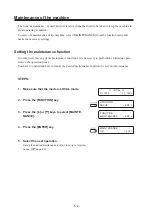
Page 88: ...ny of the maintenance functions it is necessary to perform the following opera tion on the operation panel You have to understand how to invoke the desired maintenance function to carry out maintenance STEPS 1 Make sure that the mode is LOCAL mode 2 Press the FUNCTION key 3 Press the or keys to select MAINTE NANCE 4 Press the ENTER key 5 Select the next operation Set up the desired maintenance fun...

Page 89: ...Nozzle Clean Ink Filling Fill up the ink Perform it when nozzle clogging is still not solved In addition when Nozzle cleaning or Storage Wash is performed this may cause color mixture Perform it when ejecting mixed color ink Ink Change This is not normally used Information Display the firmware versions of this machines and an interface Routine Ctrl To set Routine Flushing or Routine Cleaning on of...

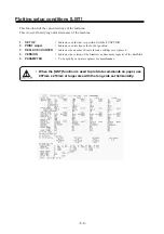
Page 90: ...2 PRINT adjust Indicates a correction value for dot position 3 REPLACE COUNTER Indicates the number of times the ink cartridges are replaced 4 VERSION Indicates the version of the firmware and memory capacity of the machine 5 PARAMETER To be used by customer engineer for maintenance When the LIST function is used to plot data commands on paper use 297mm x 210mm or larger size with the long side se...

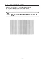
Page 91: ... HEX code The HEX code is an alphanumeric representation of plotting commands By using this code it is possible to check if there are any abnormal data commands When the DATA DUMP function is used to plot data commands on paper use 297mm x 210mm or larger size with the long side set hori zontally ...

Page 92: ...Press the ENTER key Plotting of the test patterns for the correction of dot position starts There are seven types of test patterns that are plotted 5 Press the XY or keys to correct the dot position of pattern 1 The seven test patterns that are output are sequentially named PATTERN 1 to PATTERN 7 Select the correct dot positions on PATTERN 1 pressing the XY or keys Select the dot positions that ma...

Page 93: ...ion correction value on Patterns 1 to 7 and then terminate dot position correction 8 Press the END key to complete Print Adjust 9 Press the END key twice and the menu returns to the LOCAL mode Print Adjust Pattern2 0 0 MAINTENANCE Print Adjust ent LOCAL X 1010 Y 1860 Print Adjust Pattern3 0 0 Print Adjust Pattern4 0 0 Print Adjust Pattern5 0 0 Print Adjust Pattern6 0 0 Print Adjust Pattern7 0 0 Pr...

Page 94: ...carriage STEPS 1 Press the or keys to select Station 2 Press the ENTER key 3 Press the ENTER key 4 Open the station cover then perform the fol lowing maintenance works for the station interior 1 Cleaning the ink caps page 3 4 2 Cleaning the wiper page 3 4 3 Cleaning the ink at the bottom of the slider page 3 3 4 Replacing the flushing tray ink absorber page 3 11 5 Replacing the wiper page 5 9 When...

Page 95: ...details refer your dealer STEPS 1 Press the or keys to select Station 2 Press the ENTER key 3 Press the or keys to select Wiper Excng 4 Press the ENTER key The wiper moves toward you and the carriage moves away from the station 5 Open the station cover 6 Take off the wiper with holding projections at the tips of wiper Use the gloves that are supplied with the separately available clean wiper to pr...

Page 96: ...r guide shaft using a cotton swab or cloth If dirt is hard to remove use a cotton swab of cloth damp ened with cleaning liquid Cleaning the wiper guide shaft page 3 4 Extremely dirty wiper guide shaft may cause operation failure of the wiper resulting in error display 9 Check the flushing tray ink absorber Replace if ink is found on the ink absorber page 3 11 10 Close the station cover then press ...

Page 97: ...ed 2 Press the or keys to select MAINTE NANCE 3 Press the ENTER key 4 Press the or keys to select Ink Filling 5 Press the ENTER key 6 Press the XY or keys to select a head with no ink 1256 3478 ABEF CDGH 7 Press the XY or keys to indicate a head with no ink by 8 Press the ENTER key 9 When filling up some ink back to STEP 4 FUNCTION SETUP ENT FUNCTION MAINTENANCE ENT MAINTENANCE List ent MAINTENANC...

Page 98: ... keys to select the dis playing level for changing a wiper 1 1 Several times of the standard wiping displays the warning for changing a wiper Initial value 1 2 A half time of the standard wiping displays the warning for changing a wiper 1 3 A third time of the standard wiping displays the warning for changing a wiper 1 4 A quarter time of the standard wiping displays the warning for changing a wip...

Page 99: ...sure that the FUNCTION mode is dis played 2 Press the or keys to select the MAINTE NANCE 3 Press the ENTER key 4 Press the or keys to select the Informa tion 5 Press the ENTER key 6 Select Version then press the ENTER key 7 Press the END key for times and the menu returns to the LOCAL mode LOCAL X 1010 Y 1860 FUNCTION SETUP ENT FUNCTION MAINTENANCE ENT MAINTENANCE Station ent MAINTENANCE Informati...

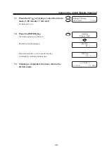
Page 100: ...line STEPS 1 Press the or keys to select Use Head 2 Press the ENTER key 3 Press the XY or keys to select the use head 4 Press the ENTER key 5 Press the END key twice and the menu re turns to the LOCAL mode MAINTENANCE Use Head ent Use Head Head Line L 12 LOCAL X 1010 Y 1860 MAINTENANCE Use Head ent Use Head Head Line L1234 Head Line L 234 Head Line L123 Head Line L 34 Head Line L 23 Head Line L 4 ...

Page 101: ...ON mode is dis played 2 Press the or keys to select MAINTE NANCE 3 Press the ENTER key 4 Press the or keys to select Routine Ctrl 5 Press the ENTER key 6 Select Routine Flushing then press the EN TER key 7 Press the or keys to select ON 8 Press the ENTER key 9 Press the or keys and select time inter val 10 Press the ENTER key FUNCTION SETUP ENT FUNCTION MAINTENANCE ENT MAINTENANCE Station ent MAIN...

Page 102: ...eys to select Routine Ctrl 5 Press the ENTER key 6 Select Routine Cleaning then press the ENTER key 7 Press the or keys to select ON 8 Press the ENTER key 9 Press the or keys and select time inter val 10 Press the ENTER key FUNCTION SETUP ENT FUNCTION MAINTENANCE ENT MAINTENANCE Station ent MAINTENANCE Routine Ctrl ent Routine Control Select Cleaning Routine Cleaning Cleaning OFF Routine Cleaning ...

Page 103: ...asures to be taken in the case where an to be taken in case an abnormal condition arises and an error message appears on the display Table of contents Abnormal conditions where no error massage appears 6 2 If image quality declines 6 3 Problems where error messages are given on the LCD 6 4 ...

Page 104: ...nected to the power outlet and the computer The machine cannot perform plotting This occurs when the data is not being transmitted to the machine properly It can also occur when any of the machine functions fails or the medium has been set improperly Has the power cable been connected to the machine and the receptacle Securely connect the power cable to them If it Is the correct interface cable us...

Page 105: ...cters fluctuate doubly or triply into paper feed Corrective measure Conduct the Feed Correct function page 2 15 Displacement is observed between outward and inward plotting The respective color ink injected by the respective color heads do not properly overlap Corrective measure Conduct the Print Adjust function page 5 6 Large ink drop on medium Corrective measure 1 Clean the wiper page 3 4 2 Clea...

Page 106: ... ink cartridge is insufficient The ink cartridge has run out of ink Attach the ink cartridge s corresponding with the number s shown on the display Printing can continue by pressing the REMOTE key However it is recommended that you replace the ink cartridge is shown on the LCD with a new one Replace the ink cartridge shown on the LCD with a new one The ink cartridge will expire soon or has expired...

Page 107: ...It indicates when the filter at the right left absorption table must be replaced Head stays uncapped for more than 30 seconds Time to replace regularly replaceable parts Replace the battery Plotting will be enabled by press ing the REMOTE Then the error message will not appear until the power is returned on It is recommended however to replace the wiper with a new one as soon as possible The batte...

Page 108: ...perature Evn Temp is Low Temperature Evn Temp is High Temperature is below operable condition Temperature is below guaran teed Temperature is over below guaranteed Adjust environmental temperature Warning message Cause Corrective measure ...

Page 109: ... 08 LINEAR ENCODER ERROR 09 FPGA ERROR 19 HDC ERROR 10 COMMAND Control circuit board is defective Control circuit board is defective POWER 5V POWER 35V Control circuit board is defective Head connection failure is detected Trouble with detection of linear encoder Control circuit board is defective FPGA Error HDC Error The device has received data other than command data The interface cable used is...

Page 110: ...n overload The Ymotor has been overload Overcurrent error on the Xmotor has been detected Overcurrent error on the Ymotor has been detected Incorrect height of the capping station has been detected Check the host computer output setting Turn off the power to the machine for a while and then turn it on If the same error message appears again on the LCD contact your local distributor for service Che...

Page 111: ...measure The wiper position is not correct Origin could not be detected Turn off the power to the machine for a while and then turn it on If the same error message appears again on the LCD contact your local distributor for service Problems where error messages are given on the LCD ...

Page 112: ... 6 10 ...

Page 113: ...cribes the specifications of the machine and components and the structure of the function menu Table of contents Basic specifications A 2 Ink specification A 4 Consumable items A 5 Location of safety labels A 6 Function flowchart A 8 ...

Page 114: ...ied media with a flat surface such as cardboards and tiles Sheet like works cloth canvas PET synthetic paper etc Work size Max printing area 1860 x 1010 mm Max setting size 1870 x 1050 mm Thickness 50 mm or less Weight 60kg or less when load is evenly distributed Distance Absolute accuracy Whichever the larger one of 0 3 mm or 0 15 of the designated accuracy Reproducibility Whichever the larger on...

Page 115: ...500VA Separate power is required for blower Recomended Available temp 15 C 30 C Environment Humidity 40 65 Rh No condensation Guaranteed temp 18 C 25 C Temperature change 10 C h or less Dust Equivalent to normal office level Weight 650 Kg Outside dimensions 3070 W x 2560 D x 1350 H mm or less Leser sensor unit specifications Item Specifications Type JIS IEC Class I Laser Product Maximum output 3 0...

Page 116: ...20 cc per cartridge ES3 ink 440 cc per cartridge Shelf life Depending on the description of the cartridge Within six months after opening the package Storage temperature During storage 0 25 C average temperature of a day During 20 60 C if it is 20 C or 60 C within 48 hours Do not disassemble or refill the ink cartridge ...

Page 117: ...t regular intervals to maintain adequate printing quality Contact your local MIMAKI distributor or call a local MIMAKI office for services Wiper 10pcs Order No SPA 0116 Ink absorber for the flushing tray 100pcs Order No M 3 Cotton swabs 10pcs Wooden axis S cotton swab 6 ...

Page 118: ...hed to this machine If any of them fall off or become illegible contact MIMAKI local distributor for a replacement All persons who install operate and maintain this machine should understand and follow the safety precautions in these labels Failure to do so can result in serious injury 6 4 5 2 1 3 1 6 7 7 2 ...

Page 119: ... A 7 Location of safety labels 1 M903968 2 LHDM 04 Japanese PED 04 English 3 M901469 4 M901607 5 M901549 6 M903226 Japanese M904325 English 7 LHCM 02 Japanese PEC 02 English No Order No Label ...

Page 120: ... 12 5678AB EFGH ENTER ENTER 12345678901234567890123456 12345678901234567890123456 12345678901234567890123456 12345678901234567890123456 12345678901234567890123456 12345678901234567890123456 12345678901234567890123456 12345678901234567890123456 No intercivic filling 12345678901234567890123456 12345678901234567890123456 12345678901234567890123456 12345678901234567890123456 12345678901234567890123456...

Page 121: ...nk Type Type Sol Ink Type Type Sol Filling 00 00 00 Ink Cartridge ABCDEFGH Filling 00 00 00 Display remaining time Display remaining time Display remaining time No ink cartridge Ink type in parameter is displayed Ink type in parameter is displayed Ink type in parameter is displayed Function flowchart ...

Page 122: ...23456789012345 L 1 Origin Setup Origin Origin Setup X Y Head Height mm Head Height mm VIEW ENT VIEW DATA CLEAR ENT CLEAR X DATA VIEW 1234567890123456789012345 1234567890123456789012345 1234567890123456789012345 1234567890123456789012345 1234567890123456789012345 1234567890123456789012345 1234567890123456789012345 1234567890123456789012345 L 2 TEST ENTER TEST PRINT ENT PRINT TEST Z X XY JOG MODE Z ...

Page 123: ...2345678901234567890123456 12345678901234567890123456 12345678901234567890123456 12345678901234567890123456 12345678901234567890123456 12345678901234567890123456 12345678901234567890123456 12345678901234567890123456 Return to LOCAL 12345678901234567890123456 12345678901234567890123456 12345678901234567890123456 12345678901234567890123456 12345678901234567890123456 12345678901234567890123456 1234567...

Page 124: ...34567890123456789012345 1234567890123456789012345 L 2 Clean 12563478 Select ABEFCDGH CLEANING ENTER Cleaning Type Normal REMOTE TYPE X Y REMOTE V360x360 STD 4P U Feed Comp 50 Adjust ent Feed Comp 50 Adjust 100 1234567890123 1234567890123 1234567890123 1234567890123 Online 1234567890123 1234567890123 1234567890123 1234567890123 Feed Comp Receiving Data Near End ENTER ENTER ENTER ENTER X Soft Strong...

Page 125: ...90123456789012345678 1234567890123456789012345678 1234567890123456789012345678 1234567890123456789012345678 Display when Ink Near End occurs Alternataly display Display remaining time ENTER REMOTE V360x360 STD 4P U Ink Near End 12 5678AB EFGH CYCLE V360x360 STD 4P U Alternataly display Function flowchart ...

Page 126: ...4567890123456789012345 1234567890123456789012345 1234567890123456789012345 1234567890123456789012345 1234567890123456789012345 1234567890123456789012345 1234567890123456789012345 1234567890123456789012345 L 3 Ink Level 9999999999999999 Head Height mm ENTER ENTER FUNCTION 123456789012345 123456789012345 123456789012345 123456789012345 Guidance display The remaining ink are display with level 0 to 9...

Page 127: ...ype Type TPig Ver1 00 MRL IIC SETUP TYPE Display V Key Error Info Display V Key ENTER X Shows all currentry occurred err Display current set ink Display FW ver and Command X Shows currently SETUP condition Function flowchart ...

Page 128: ...2345 1234567890123456789012345 1234567890123456789012345 1234567890123456789012345 1234567890123456789012345 S 1 1234567890123456789012345 1234567890123456789012345 1234567890123456789012345 1234567890123456789012345 1234567890123456789012345 1234567890123456789012345 1234567890123456789012345 1234567890123456789012345 S 3 FUNCTION SETUP ENT SETUP SELECT TYPE1 TYPE PrintMode ent ENTER ENTER ENTER ...

Page 129: ...irection UNI D TYPE Layer 1 TYPE Time 0 0s TYPE PrintMode HOST TYPE Ink Layers HOST TYPE HOST TYPE Media Comp HOST TYPE Refresh HOST X Fine X BI D X 1 9 X 0 0 9 9s X PLOT X PLOT X PLOT X PLOT X PLOT ENTER ENTER HighSPD TYPE Logicalseek ON X OFF ENTER Function flowchart X OFF ...

Page 130: ...890123456789012345 1234567890123456789012345 1234567890123456789012345 S 2 1234567890123456789012345 1234567890123456789012345 1234567890123456789012345 1234567890123456789012345 1234567890123456789012345 1234567890123456789012345 1234567890123456789012345 1234567890123456789012345 S 3 1234567890123456789012345 1234567890123456789012345 1234567890123456789012345 1234567890123456789012345 123456789...

Page 131: ... A 19 TYPE Refresh Level3 TYPE mm inch mm X Level0 Level3 X inch Function flowchart ...

Page 132: ...90123456789012345 1234567890123456789012345 1234567890123456789012345 1234567890123456789012345 1234567890123456789012345 1234567890123456789012345 S 5 1234567890123456789012345 1234567890123456789012345 1234567890123456789012345 1234567890123456789012345 1234567890123456789012345 1234567890123456789012345 1234567890123456789012345 1234567890123456789012345 M 1 TYPE Media Comp ent TYPE AutoClean e...

Page 133: ...23 1234567890123 Output END X Y Width X OFF Y 12345678901234567890123456 12345678901234567890123456 12345678901234567890123456 12345678901234567890123456 12345678901234567890123456 12345678901234567890123456 12345678901234567890123456 12345678901234567890123456 Initialize the Parameter TYPE ColorPatn OFF X 100 1000 X ON Function flowchart ...

Page 134: ...456789012345 1234567890123456789012345 1234567890123456789012345 1234567890123456789012345 M 1 FUNCTION MAINTENANCE ENT MAINTENANCE List ent 1234567890123456789012345 1234567890123456789012345 1234567890123456789012345 1234567890123456789012345 1234567890123456789012345 1234567890123456789012345 1234567890123456789012345 1234567890123456789012345 M 3 List Print ent ENTER MAINTENANCE Data Dump ent ...

Page 135: ...456789012345 1234567890123456789012345 1234567890123456789012345 1234567890123456789012345 1234567890123456789012345 1234567890123456789012345 1234567890123456789012345 Return to Origin 1234567890123 1234567890123 1234567890123 1234567890123 Output 123456789012345 123456789012345 123456789012345 123456789012345 Receiving Data ENTER END END Y Function flowchart ...

Page 136: ...90123456789012345 1234567890123456789012345 1234567890123456789012345 1234567890123456789012345 1234567890123456789012345 M 5 1234567890123456789012345 1234567890123456789012345 1234567890123456789012345 1234567890123456789012345 1234567890123456789012345 1234567890123456789012345 1234567890123456789012345 M 3 MAINTENANCE Station ent Station Maint Sel CarriageOut 1234567890123456789012345 12345678...

Page 137: ... ENTER Carriage Out Completed ent Initialize Please Wait Wiper Cleaning Completed ent Initialize Please Wait Wiper Exchange Completed ent ENTER Fill Up Washing Completed ent Nozzle Cleaning WaitTimer 1min Color May Mix Up ContinueOK ent Initialize Please Wait Waiting 00 00 00 Cleaning 00 00 00 ...

Page 138: ...234567890123456789012345 1234567890123456789012345 1234567890123456789012345 1234567890123456789012345 1234567890123456789012345 1234567890123456789012345 M 5 1234567890123456789012345 1234567890123456789012345 1234567890123456789012345 1234567890123456789012345 1234567890123456789012345 1234567890123456789012345 1234567890123456789012345 M 8 1234567890123456789012345 1234567890123456789012345 123...

Page 139: ...ialize Please Wait ENTER ENTER Wiper Cleaning Completed ent Fill Up Washings Completed ent Nozzle Cleaning WaitTime 1min X 1 99min Initialize Please Wait Storage Wash 00 00 00 Cleaning 00 00 00 Wiper Cleaning Completed ent Drain Wash Completed ent Initialize Please Wait ENTER ENTER ENTER ENTER ...

Page 140: ...4567890123456789012345 1234567890123456789012345 1234567890123456789012345 1234567890123456789012345 1234567890123456789012345 1234567890123456789012345 M 10 1234567890123456789012345 1234567890123456789012345 1234567890123456789012345 1234567890123456789012345 1234567890123456789012345 1234567890123456789012345 1234567890123456789012345 M 8 MAINTENANCE Ink Filling ent X Head On Off Y Move cursor ...

Page 141: ... A 29 MAIN Ver1 00 I F Ver Function flowchart ...

Page 142: ...789012345 1234567890123456789012345 1234567890123456789012345 1234567890123456789012345 1234567890123456789012345 M 10 FUNCTION X ENTER ENTER Routine Control Select Flushing MAINTENANCE RoutineCtrl ent X ENTER Use Head HeadLine L1234 MAINTENANCE Use Head ent XY L 234 L123 L 34 L 23 L12 L 4 L 3 L 2 L1 FUNCTION X Routine Control Select Cleaning FUNCTION X X ENTER ENTER FUNCTION DISPLAY ENT DISPLAY E...

Page 143: ... A 31 Routine Cleaning Cleaning ON ENTER Routine Cleaning Interval 1h X OFF X 1 48h Routine Flushing Flushing ON ENTER Routine Flushing Interval 1h X OFF X 1 24h Function flowchart ...

Page 144: ...D201258 1 10 30032007 ...

Page 145: ......

Page 146: ...PrintedinJapan MIMAKI ENGINEERING Co Ltd FW 5 10 NH ...

Reviews: