background image

– 5.6 –

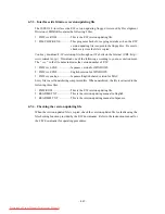
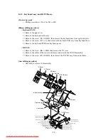
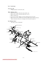
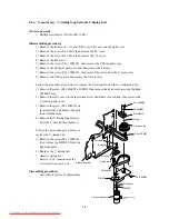
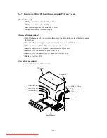
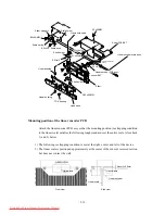
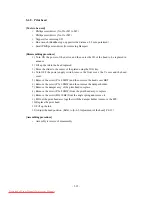
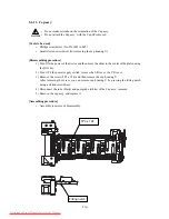
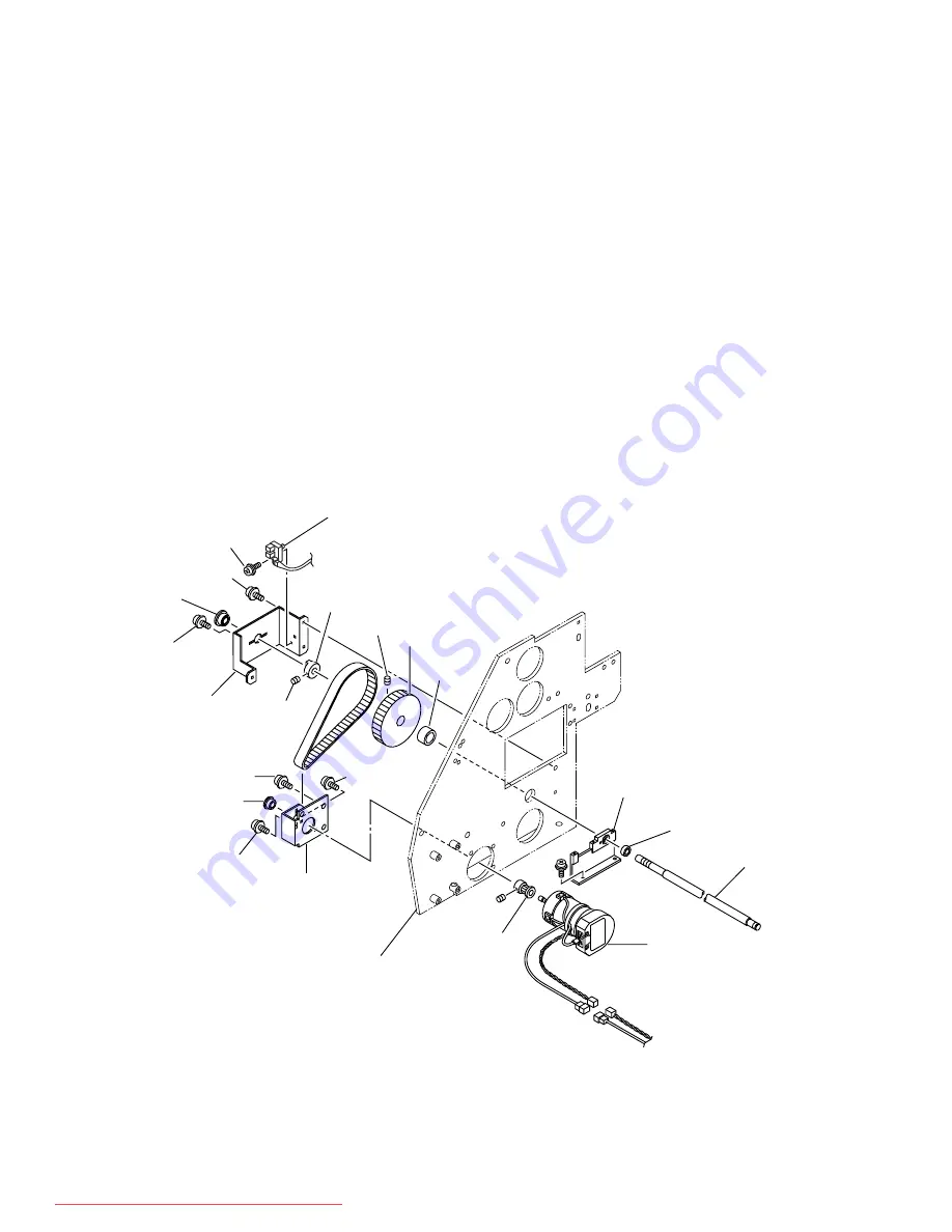
5-1-4.  X-motor assy.

[Tools to be used]

Phillips screwdriver (No.2 for M3 to M5)

[Disassembling procedure]

1) Remove the screw (B3 x 6Ni), then remove the SL cover.

2) Remove the screw (B3 x 6Ni), then remove the YL cover.

3) Remove the left cover.

4) Loosen the screw (P4 x 8SMW) in the X-motor BKT from the left side plate.

5) Remove the screw (P3 x 6SMW) from  the X-motor BKT, then remove the X-motor assy.

*

Adjust Y-timing belt : Refer to [6-2-5. Adjustment of the X-motor belt tension] P.6-11

[Assembling procedure]

Assembly is reverse of disassembly.

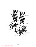
to Main PCB assy.  CN20

to Main PCB assy.  CN6,7

B3 x10Bk

P4 x8SMW

P3 x6SMW

P4 x8SMW

P4 x8SMW

P3 x6SMW

SSWP4

XM BKT

Bearing

X-Origin sensor assy.

Pulley stopper

SSWP4

TN15-20 Pulley

Bushing

XM BKT

Bearing

Left side plate

Bearing

Bearing holder 1

X-joing shaft

X-axis motor assy.

TN-15-160 Pulley

SSWP4

Downloaded From ManualsPrinter.com Manuals

Summary of Contents for JV4-130

Page 1: ...a Building 5 9 41 Kitashinagawa Shinagawa ku Tokyo 141 0001 Japan Phone 81 3 5420 8671 Fax 81 3 5420 8687 URL http www mimaki co jp E mail traiding mimaki co jp MAINTENANCE MANUAL Ver 1 00 D500175 Downloaded From ManualsPrinter com Manuals ...

Page 2: ...Downloaded From ManualsPrinter com Manuals ...

Page 3: ...earned disassembly assembly and adjustment techniques with required tools and measuring apparatues This manual covers existing maintenance parts For any failure other than those described in this manual factory repairs will be necessary Before reading this maintenance manual read the following manual to learn basic operations of this device Instruction Manual for JV4 Series D200571 Downloaded From...

Page 4: ... 11 The KeyBoard PCB 2 13 2 1 12 Ink Sensor PCB 1 2 13 2 1 13 Ink Sensor PCB 2 2 13 2 1 14 Take up motor PCB 2 13 2 2 Ink system 2 14 2 2 1 Definitions 2 14 2 2 2 Brief explanation of the ink system 2 15 2 2 3 Parameters related to the ink system 2 18 2 3 Brief explanation of media size detection control 2 19 CHAPTER 3 TROUBLESHOOTING 3 1 3 1 Troubles for which error messages are given on the LCD ...

Page 5: ...e Stripes on Reverse Sides 3 19 3 4 8 Dark and Light Images Occur at Each Scan 3 19 3 4 9 Stripes occur 3 20 CHAPTER 4 MAINTENANCE MODE 4 1 4 1 Maintenance items 4 2 4 2 Entering into the maintenance mode 4 3 4 2 1 Entering into the maintenance mode when actuating the plotter 4 3 4 2 2 Entering into the maintenance mode by system parameters 4 4 4 3 Menu of ADJUST 4 5 4 3 1 PRINTadjust2 4 5 4 3 2 H...

Page 6: ... 6 ADJUSTMENT PARAMETER 4 62 4 5 7 INFORMATION PARAMETER 4 62 4 6 Uploading and Downloading Parameters 4 63 4 6 1 UPLOAD Plotter Computer 4 63 4 6 2 DOWNLOAD Computer Plotter 4 64 4 7 Updating the firmware 4 66 4 7 1 The firmware in this unit 4 66 4 7 2 Main unit side firmware version updating file 4 66 4 7 3 Interface side firmware version updating file 4 67 4 7 4 Checking the version updating fi...

Page 7: ...nsor assy and Wipersensor assy 5 17 5 1 13 IEEE1394 PCB Main PCB HDC 4 Head PCB assy HDC 2 Head PCB assy and Power PCB 5 19 5 1 14 Ink supply tube inside diameter ø2mm 5 21 CHAPTER 6 ADJUSTMENT 6 1 6 1 Adjusting item list 6 2 6 2 Adjusting item 6 3 6 2 1 Adjustment of the cutter height 6 3 6 2 2 Adjustment of the station position 6 4 6 2 3 Adjustment of the Linear sensor PCB assy height 6 9 6 2 4 ...

Page 8: ... vi Downloaded From ManualsPrinter com Manuals ...

Page 9: ... 1 1 CHAPTER 1 OVERVIEW OF MAINTENANCE Downloaded From ManualsPrinter com Manuals ...

Page 10: ...ter in such a way when ascending descending the stairs that the maintenance station is lower than the ink station In principle the following procedure should be taken in prior to the transportation 1 Discharge ink from the tube in accordance with the description given under Discharge cleaning in the maintenance tests 2 Detach the waste ink tank 3 Fix the head with the head stopper If the main unit...

Page 11: ... 1 Log side 2 5 mm for drawing out E rings Hexagon wrench key 1 1 5 mm for M3 SSWP 1 2 0 mm for M4 SSWP 1 2 5 mm for M3 cap bolts 1 5 5 mm for hexagon stud 1 6 0 mm for M8 cap bolts Wrench 1 Opposite side 5 mm 1 Opposite side 5 5 mm for M3 nuts 1 Opposite side 7 mm for M4 nuts Tweezers 1 To prevent the cable from being pulled when disconnecting the connector Long nose pliers 1 Nippers 1 Soldering ...

Page 12: ...aying set items etc 7 Maintenance cover This is the carriage cover During maintenance of the station open it by loosening the screws 8 Clamp lever It is made to go up down the pinch roller for holding medium 9 Waste ink tank Waste ink gathers in this tank One waste ink tank is provided on each side of the device 10 Stand It supports the main unit It is provided with casters that are used to move t...

Page 13: ...inserted in the right and left core of roll medium to hold the roll medium The roll holder is applicable to diameter of medium cores with 2 and 3 inches 4 Paper roll setting bar This bar facilitates a paper roll to be set in position 5 Ink cartridge Each cartridge contains ink of a specific color 6 R ink station This station houses up to six ink cartridges Downloaded From ManualsPrinter com Manual...

Page 14: ...dium Mat PVC Tarpaulin Back lit film Cloth Nonflamable cloth Other Artwork film Canvas Tarpaulin Waterproof olefin film Board Max Printing width Width 1371 mm Width 1600 mm Width 1870 mm Medium size Maximum 1381 mm 1620 mm 1910 mm Leaf medium Minimum 210 mm Medium size Thickness 1 0 mm or less Roll medium Roll outside diameter Ø 150 mm or less Roll weight 20 Kg or less Roll inside diameter 2 Inch ...

Page 15: ...ise during continuous printing Less than 66 dB Noise during discontinuous printing Less than 70 dB Safety Standard FCC ClassA Power AC 100 240 V 120 W or less Power consumption 400 W or less Recomended Temperature 15 C to 30 C Enviroment Humidity 35 to 65 Rh No condensation Temperature change 10 C h or less Dust Equivalent to normal office level Outside dimensions mm 2406 x 730 x 1220 2740 x 730 x...

Page 16: ...s 12 minutes 08 seconds Variable Fine 16 21 minutes 37 seconds 38 minutes 47 seconds Speed 4 5 minutes 38 seconds 10 minutes 40 seconds 1440 x 720 Standard 8 6 minutes 06 seconds 12 minutes 08 seconds Variable Fine 16 21 minutes 37 seconds 38 minutes 42 seconds Speed 16 22 minutes 35 seconds 42 minutes 43 seconds 1440 x 1440 1 Standard 16 22 minutes 35 seconds 42 minutes 43 seconds Fine 32 44 minu...

Page 17: ...90µm or more is recommended If the dot size is small make plotting in the 6 pass mode or higher mode to make panting less distinctive These modes need less amount of feed improving the accuracy Panting can also be reduced through software processing 360 x 720 Tarpaulin media etc Use media with high ink absorption factor 720 x 720 Glossy media Since the 4 pass mode is subject to panting by media fe...

Page 18: ... 1 10 Downloaded From ManualsPrinter com Manuals ...

Page 19: ... 2 1 CHAPTER 2 EXPLANATION OF OPERATION Downloaded From ManualsPrinter com Manuals ...

Page 20: ...le data is transferred to the head Y directional position adjustment can be made in units of one dot or less by adjusting the timing of the COM waveform for each nozzle row Since the ink discharge performance depends on each head the COM waveform is corrected automatically based on the head ID registered and the ambient temperature detected If the head ID is not registered correctly no ink may be ...

Page 21: ...PER SENSOR CN26 CN27 CN3 CN2 CN5 CN6 CN4 CN14 CN28 CN2 CN10 CN3 CN11 CN4 CN12 CN5 CN13 CN6 CN14 CN7 CN15 CN8 CN16 30 5V SEN SIG GND FPC 40 42V HEAD1 GND FPC 40 42V HEAD2 GND FPC 40 42V HEAD3 GND FPC 40 42V HEAD4 GND FPC 40 42V HEAD6 GND FPC 40 42V HEAD5 GND FPC IO BOARD HDC 2 Head BOARD HDC 4 Head BOARD COLD FAN 5VSIRIAL SIG GND FPC CN17 FRONT COVER SENSOR SW SLIDER BOARD CAPPING SENSER CN3 CN2 EN...

Page 22: ...e SH 3 RISC 133MHz from Hitachi is used as the CPU The program of the CPU is stored in the flash memory This program can easily be upgraded on site through the interface During upgrading the program is downloaded to the PRAM by the CPU and then stored in the flash memory of the CPU When the receive data is read from the interface the CPU loads the data in the picture memory through the PDC CTR The...

Page 23: ... 2 5 Main PCB block diagram Downloaded From ManualsPrinter com Manuals ...

Page 24: ... V1 CN5 CN6 CN7 CN8 CN9 CN10 CN13 Connector Pin No Signal Name Remarks 1 5V 2 GND 3 SPCK I2 3 4 SPLD I2 3 5 SPDA I2 3 6 SPCK O3 4 7 SPLD O3 4 8 SPDA O3 4 9 ID IN Not used 10 ID OUT Not used 11 GATE 12 N C A1 35V A2 35V A3 35V A4 N C A5 N C A6 IFRESET A7 IF RDnWR A8 PWDWN Not used A9 WUPRQ Not used A10 IF nPREQ A11 IF DRQ0 A12 IF DRQ1 A13 INNDREQ3 Not used A14 INNDREQ4 Not used A15 IFA0 A16 IFA1 A1...

Page 25: ...CK 3 GND 4 SNLD1 2 5 D0 6 D1 7 D2 8 D3 9 D4 10 D5 11 D6 12 D7 13 GND 14 SDI1 2 15 SDRQ1 2 16 HNINTR1 2 17 REJ1 3 18 REJ2 4 19 SUB1 3 20 SUB2 4 21 LE1 2 A 22 LE1 2 B 23 LE1 2 A R 24 LE1 2 B R 25 GND 26 40MSCK 27 40MSCK 28 GND 29 3 3V 30 3 3V 31 GND 32 GND 33 5V 34 5V 35 GND 36 35V 37 35V 38 35V 39 35V 40 35V CN18 CN19 CN17 Connector Pin No Signal Name Remarks 1 5V 2 UDINO 3 UDINI Not used 4 GND 1 C...

Page 26: ...er circuit for the cooling fan and cutter and the read out circuit for the paper width sensor and temperature sensor HDC PCB Connector signals Connector Pin No Signal Name Remarks 1 GND 2 SCK 3 GND 4 SNLD1 2 5 D0 6 D1 7 D2 8 D3 9 D4 10 D5 11 D6 12 D7 13 GND 14 SDI1 2 15 SDRQ1 2 16 HNINTR1 2 17 REJ1 3 18 REJ2 4 19 SUB1 3 20 SUB2 4 21 LE1 2 A 22 LE1 2 B 23 LE1 2 A R 24 LE1 2 B R 25 GND 26 40MSCK 27 ...

Page 27: ... GND 37 GND 38 HxCOMA 39 HxCOMA 40 HxCOMA 1 GND 2 OUTA 3 OUTA 4 GND 5 OUTB 6 OUTB 7 GND 8 HxCHGB 9 GND 10 HxLATB 11 GND 12 HxCHB 13 GND 14 HxNCHGA 15 GND 16 HxLATA 17 GND 18 HxCHA 19 GND 20 OUTC 21 OUTC 22 GND 23 OUTD 24 OUTD 25 GND 26 5V 27 5V Connector Pin No Signal Name Remarks 28 GND 29 GND 30 42V 31 GND 32 HxCOMB 33 HxCOMB 34 HxCOMB 35 GND 36 GND 37 HxCOMA 38 HxCOMA 39 HxCOMA 40 GND 1 24V 2 3...

Page 28: ...2 Paper sensor 3 GND 1 5V 2 D3 Station sensor 3 N C 4 GND 1 5V 2 D4 Wiper sensor 3 N C 4 GND 1 POWER F 2 POWER F 1 POWER Not used 2 POWER 1 POWER M Take up motor 2 POWER M Take up motor 3 5V 4 W ENC Not used 5 W SEN Not used 6 GND 7 GND 8 W UNIT Not used 9 GND 1 POWER L 2 GND 3 LAMP Not used 1 MA P1 2 N C 3 MA P1 4 MB P1 5 N C 6 MB P1 1 MA P2 2 N C 3 MA P2 4 MB P2 5 N C 6 MB P2 CN2 CN14 CN3 CN4 CN...

Page 29: ...17 A4INH3 18 A4INH2 19 A4INH1 20 A4C 21 A4B 22 A4A 23 ASCK 24 ACS 25 GND 26 GND 27 5V 28 5V 29 5V 30 GND CN17 CN18 2 1 9 Slider PCB The slider PCB is located on the inner side of the head cover It relays the head control signal and head driving signal from the HDC PCB to the print heads It contains the sensor circuit which detects the signal from the thermistor on each head and the signal from the...

Page 30: ...A 4 OUTA 5 GND 6 OUTB 7 OUTB 8 GND 9 HxNCHGB 10 GND 11 HxLATB 12 GND 13 HxCHB 14 GND 15 HxNCHGA 16 GND 17 HxLATA 18 GND 19 HxCHA 20 GND 21 OUTC 22 OUTC 23 GND 24 OUTD 25 OUTD 26 GND 27 5V 28 5V 29 GND 30 GND 31 42V 32 GND 33 HxCOMB 34 HxCOMB 35 HxCOMB 36 GND 37 GND 38 HxCOMA 39 HxCOMA 40 HxCOMA 1 GND 2 OUTA 3 OUTA 4 GND 5 OUTB 6 OUTB 7 GND 8 HxCHGB 9 GND 10 HxLATB 11 GND 12 HxCHB 13 GND 14 HxNCHGA...

Page 31: ...ght cover It passes on signals among the ink cartridge presence absence sensors for ink cartridges ink end sensor and main PCB 2 1 13 Ink Sensor PCB 2 Sensor PCB 2 is on the left hand side plate it relays signals among the ink cartridge presence absence sensors for ink cartridges the ink end sensors and the main PCB 2 1 14 Take up motor PCB This board located in the take up device drivers the moto...

Page 32: ...ince a specific nozzle has failed to discharge ink straight on the paper because of the dust accumulated or damaged nozzle surface Satellite Discharged ink is shot as main drops or satellite drops If satellite drops are contained in main drops the ink shot may shift Head cleaning Recovers normal ink discharge by removing bubbles in the head and foreign objects on the head surface Wiping Wipes the ...

Page 33: ...rvals Ink end monitoring After a lapse of 3 seconds after Standby operation the completion of scanning Power to the device is turned off Parameters are saved on FROM 2 2 2 Brief explanation of the ink system The ink system control mainly contains the following functions Processing when turning the power on Processing when starting plotting Refreshing operation Standby operation Ink end monitoring ...

Page 34: ...ed standby time to avoid defective ink ejection on account of increased ink viscosity Refreshing operation During plotting only some of the nozzles discharge ink To prevent nozzles that are at rest from drying and ink from thickening the head is moved onto the cap inside of the station at fixed intervals and ink is ejected from all nozzles to maintain stable ink ejection The refresh interval and t...

Page 35: ...n particular when ink has not yet passed through the head at all when the plotter is shipped from the factory initial filling of ink is carried out so that ink will pass from the ink cartridge through the tube to the head Miscellaneous a The cap inside the station must be kept at the proper humidity to prevent the nozzle from drying out For this reason whenever the head is put into or taken out of...

Page 36: ... designated initial settings Ink parameters 2 Control constants used for the ink system processing are saved on They must not be changed since they are used by MIMAKI Development Division for experiments and evaluations When the main PCB has been replaced meaning that the Flash memory has been initialized the following procedure must be followed to match ink parameters 1 which control the ink syst...

Page 37: ...dia Detection by the paper width sensor Detection of the right and left side edges of a media Detection by paper width sensor Brief flow chart of the media width detection processing Edges of the media are detected through the use of the difference in lightness between the media and the platen cutter slit based on which the paper width is calculated The sensor moves to the Y coordinate of the pape...

Page 38: ... 2 20 Downloaded From ManualsPrinter com Manuals ...

Page 39: ...rouble can be determined through various tests 2 Trouble relating to the connection with the host computer Disconnection of failed contact of the cables in terms of hardware In terms of software the case where the user has changed computer parameters or has sent wrong data by mistake Recovering procedures for troubles in general that are likely to arise independently on the device will appear from...

Page 40: ...otter 2 Initial remedies Track down the cause of a trouble to the system side or the plotter side referring to the error message shown on the LCD 1 Check whether you have changed connection conditions time out setting on the host PC etc 2 Check whether or not the trouble arises under specific circumstances 3 Check whether or not the trouble is reproducible 3 Failures on the plotter side Take the f...

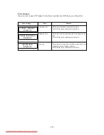
Page 41: ...eplace the main PCB with a new one 1 It is not used in the field The control ROM is in abnormal conditions The control RAM is in abnormal conditions The 35V voltage is in abnormal conditions The Flash memory is in abnormal conditions An error has occurred in the D RAM Abnormal temperature is detected The Linear encoder is in abnormal conditions Configuration of PDC IOC has not been successfully ca...

Page 42: ...e I F PCB with a new one 2 Replace the main PCB with a new one 3 Replace the I F connection board with a new one 1 Is the I F board mounted correctly 1 Is the cable loose 2 Has an error occurred on the host computer 3 Is the application being used running normally 1 Replace the I F PCBwith a new one 2 Replace the main PCB with a new one 3 Replace the main PCB with a new one 1 Indicate the improper...

Page 43: ...ht edge is set at a position 15mm or more from the rightmost edge of the rightmost feed roller R1 toward the station side or not 4 Cleaning or replace a paper width sensor 5 Replace a main FPC cable 6 Replace a slider PCB 7 Replace a HDC 4Head PCB 8 Replace a main PCB 1 Replace a Y axis motor 2 Replace a Y origin sensor 3 Replace a IO PCB 4 Replace a main PCB Media detection has not been successfu...

Page 44: ...ror recurs after the ink cartridge has been replaced conduct sensor tests to find out a possible cause of the trouble Possible causes of the troubles are as follows a The ink end sensor has failed b Defective contact or disconnection of relay cables c Ink sensor PCB has failed d The main PCB has failed 1 Replace the ink cartridge with a new one 1 Replace the wiper 1 Input the ID numbers of heads 1...

Page 45: ...that the battery has run out 1 Confirm that the computer is sending data 2 Replace the I F cable with a new one 3 Replace the 1394 PCB 4 Replace the main PCB 1 Replace the battery with a same type Message Description Corrective measures and recovering procedures REMOTE flashing display BATTERY Downloaded From ManualsPrinter com Manuals ...

Page 46: ...ble has disconnected Checking procedure 1 Check the voltage at the receptacle using a tester 2 Remove the DC cable and check the output voltage of the power supply using a tester 3 Check a resistance at 35V and 5V on the main PCB using a tester 4 Remove all the cables to be connected to the main PCB and then turn on the power See below 5 Check whether or not the LED on the main PCB is in the ON st...

Page 47: ... one 3 Replace the HDC PCB with a new one 4 Replace the slider PCB with a new one 5 Replace the main PCB with a new one 6 Refer to 3 3 9 Ink filling cannot be performed 7 Check the pump assembly 8 Perform the encoder check test 9 If the phenomenon recurs even after taking procedures 1 through 7 replace the head with a new one Remedies 1 Conduct cleaning of the head and fill up the ink 2 If the FPC...

Page 48: ...ead within the same nozzle row for example between CN9 and CN10 Do not exchange the FPC between rows A and B because of power short circuit 3 If neither row A nor row B within the same head discharges ink check the defective section by shifting the 40 wire FPC to be mounted on the slider PCB pairwise for example shift the cable of CN21 and CN22 to CN23 and CN24 Do not shift only one FPC because of...

Page 49: ...nd fully lower the cutter by hand to check whether or not the cutter comes in contact with any other component 3 Check whether or not the cutter goes up when turning the power off or detaching the connector from the slider PCB in the solenoid with the cutter held lowered abnormal state Remedies 1 Replace the cutter unit with a new one 2 Adjust the height of the cutter assy 3 Replace the HDC FPC th...

Page 50: ...e is normal the head on the R side does not contact and the wiper BKT is slanted bend the wiper BKT so that the amount of wiper contact be the same for wipers on the F and R sides 3 Perform the adjustment of the station position 3 3 7 Board medium feeding failure Problems Skew occurs The printing surface of the board makes contact with the head Causes 1 The amount of warp of the board is more than...

Page 51: ...eaning Causes 1 There are some gaps for capping 2 The pump motor has broken 3 The IO PCB has broken 4 The main PCB has broken Checking procedure 1 Visually confirm the ink filling status 2 4 Check whether or not the pump motor is running Remedies 1 Height adjustment for the station and position adjustment for capping 2 Replace the pump motor with a new one 3 Replace the IO PCB with a new one 4 Rep...

Page 52: ...dust is present on the head path above the curl stopper Checking procedure 1 Print the nozzle check to check the printed result 2 Perform cleaning to confirm that the pump is rotating and that ink is being ejected 3 Check the head ID 4 6 Visually confirm the wiper Remedies 1 Clean the head If cleaning is executed several times and the system still is not restored to correct operating condition fil...

Page 53: ...paper sensor test whether or not any abnormal value has been specified 4 Try to replace the slider PCB with a new one Try to replace the HDC PCB with a new one 5 Try to replace the main PCB with a new one 6 If the phenomenon recurs even after taking procedures 2 through 5 replace the head wtih a new one Remedies 1 If the FPC cable has disconnected replace it with a new one If the FPC cable is in p...

Page 54: ...Lc O or G some difference in colors between machines cannot be avoided 3 Replace the slider PCB or the HDC PCB with a new one 3 4 4 Plotted drawing is out of position Problems The plotted drawing is out of position Causes 1 Dust has gathered or scratches are made on the linear scale causing the linear encoder to make a detecting error Checking procedures 1 Check the linear scale for dust stains an...

Page 55: ...D stuck on the head and the ID within ADJUSTMENT 3 Is the ink securely being drained out when executing the cleaning actuation 4 Visually confirm the ink filling status 5 Aren t there any stains and whiskers due to the fibers of paper Remedies 1 Adjust the height of the head 2 Enter the correct head ID 3 Adjust the capping 4 Clean the interior of capping station and the end face of wiper 5 Use the...

Page 56: ... not correct When the media is changed perform SETUP MEDIA COMP to set values which suit the media Checking procedures 1 Perform SETUP and MEDIA COMP to check that the value of MEDIA COMP is correct 2 Medium weight measurement medium of which weight is 10kg or less is recommended 3 Check whether or not the distance compensation matches the medium used Remedies 1 Same as 1 3 4 6 Medium feeding fail...

Page 57: ...Dark and Light Images Occur at Each Scan Problems Dark and light images occur at each scan Causes 1 Slanted head 2 Gap between heads on the R and F sides or overlapped heads 3 Check wheter the ink shot size is obtained according to the resolution Checking procedures 1 Adjust the dot slant with SLANT ADJUST to 10µm or less for each color 2 Adjust the dot position with R F HEAD ADJUST to 140µm 10µm ...

Page 58: ... procedures 1 Lower the head and then make plotting Remedies 1 If panting is canceled the accuracy of the device is assumed to be normal Change the plot mode to STANDARD or FINE With 360 x 360dpi change the 2pass mode to the 4pass mode with 360 x 540dpi change the 3pass mode to the 6pass mode Downloaded From ManualsPrinter com Manuals ...

Page 59: ... 4 1 CHAPTER 4 MAINTENANCE MODE Downloaded From ManualsPrinter com Manuals ...

Page 60: ...RAW Plots the contents of the flash memory ALL PATTERN Collectively plots the adjustment condition check pattern for head or dot position X SERVO X motor aging is carried out Y SERVO Y motor aging is carried out XY SERVO XY motor aging is carried out ACTION TEST Performance of the wiper cutter and winding motor is checked SENSOR TEST Performance of various sensors is checked PAPER SENSOR Read out ...

Page 61: ...the FUNCTION key If simultaneously pressing the FUNCTION key and REMOTE LOCAL key the plotter may enter into the firmware updating mode see 4 6 Updating the firmware 2 Select the detection of media using the key key or key 3 After the detection of media the plotter will enter the LOCAL mode 4 Press the FUNCTION key in repetition and the maintenance items will appear on the LCD The item name attach...

Page 62: ...key Or simultaneously press the key and key 2 Press the key or key to call up No 62 SUPPORT on the screen 3 Press the ENTER key to enter the input mode 4 Press the key or key to input 2 or 3 0 1 Maintenance mode is disabled 2 Maintenance mode is enabled 3 Maintenance mode is enabled and the indications on the LCD are all given in English 5 Press the ENTER key to store the entered value After compl...

Page 63: ...ent values of the PRINTadjust which is open to the user become the initial values This is so that the adjustment values obtained with this function can be used as a base to which the user correction values can be added to obtain the actual dot position correction values The correction values are stored under the adijut parameters Operation 1 Select the ADJUSTMENT Press the ENTER key 2 Select the P...

Page 64: ...uch a value tha the right and left protrusions of the plotted pattern agree with each otehr 5 When plotting has been completed correction value input mode is entered Input the values using the and keys Then press ENTER key to enter the values In the follow way enter the correction values for between heads 1 and 2 between heads 1 and 3 between heads 1 and 4 between heads 1 and 5 and between heads 1...

Page 65: ... and left protrusions of the plotted pattern agree with each otehr 4 or less PRN adjust2 SEL X DIRECTION PRN adjust2 X DIR 0 0 If BASIS SET has been selected BASIS SET is a function which sets correction values for Variable 1 Normal 1 and Normal 2 based on the correction value for Variable 2 Prior to BASIS SET it is necessary to match correction values Y Si Y Re and Y Bi for Variable 2 After BASIS...

Page 66: ...of about 35µm For V1 and N1 it results in a shift of about 70µm When using a scope note that vertical and horizontal inversions occur With Y BI DIRECTIONAL FINE the above pattern is plotted only in black Make adjustment so that other lines be overlapped with the HEAD1 Black line as closely as possible However the most important is overlapping of HEAD1 and HEAD2 HEAD3 and HEAD4 and HEAD5 and HEAD6 ...

Page 67: ...NE FINAL PRN adjust2 COLOR KMC PRN adjust2 FINE Y Si Sample plotting of FINE FINAL 1 Select the Adjust FINE Press the ENTER key 2 Select the adjustment item using the or key Press the ENTER key 3 Select the color to plot Move the cursor using the or key and then select the plot color Select whether the selected color is plotted or not using the or key 4 Start plotting with the ENTER key Plot lengt...

Page 68: ...nd 6 If Y Bi D has been selected Input the correction value for the Y going and coming travel using the or key Enter the correction value between heads 1 and 1 If FINAL has been selected Enter the correction value with the ENTER key X PRINT Heads 1 3 1 5 Y SINGLE Heads 1 2 1 3 1 4 1 5 1 6 Y REPEAT Heads 1 2 1 3 1 4 1 5 1 6 Y BI D Heads 1 1 Usually processing is completed by plotting a pattern for ...

Page 69: ...key If SLANT adjust has been selected 1 Select the head REAR FRONT using the or key Press the ENTER key 2 Select the print type 720 4pass 360 2pass using the or key Press the or key to change the position only X position to plot 3 Press the ENTER key to start drawing FUNCTION ADJUST ENT ADJUST HEAD ADJUST ent HEAD ADJUST SLANT adjust ent HEAD ADJUST R F HEAD adj ent HEAD ADJUST HEAD U D adj ent HE...

Page 70: ...to select the color Display the selected color using the or key Press the ENTER key Press the or key to change the position only X position to plot Press the ENTER key to start drawing HEAD ADJUST SELECT KMc HEAD ADJUST PRINT START ent Downloaded From ManualsPrinter com Manuals ...

Page 71: ...s been filled is ejected to the waste ink tank 5 When the display shown at left appears set the cleaning tool Cleaning fluid is suctioned up 6 When the display shown at left appears remove the cleaning tool Suck in air 7 When the display shown at left appears set the cleaning tool Cleaning fluid is suctioned up 8 When the display shown at left appears remove the cleaning tool The waste ink tank di...

Page 72: ...e the cleaning tool The waste ink tank discharges the transportation fluid sucked 12 When all steps have been completed the display shown at left returns WASHING SET TRANS TOOL WASHING REMOVE TOOL ADJUST WASH ent 9 Select whether cleaning is to be continued To end cleaning press the key WASHING END CONTINUE Downloaded From ManualsPrinter com Manuals ...

Page 73: ...le suction include the wiping operation Operation 1 Select the ADJUSTMENT Press the ENTER key 2 Press the FUNCTION key to select the SELECT CLEANING Press the ENTER key 3 Select the target head using the or key Specify the target head using ENTER key FUNCTION ADJUST ENT ADJUST SELcleaning ent SELCleaning SELECT ALL SELCleaning SELECT REAR SELCleaning SELECT FRONT Cleaning operation Downloaded From...

Page 74: ... Now start the cleaning 6 Upon completion of the cleaning the indication given in step of procedure 2 will be restored on SELCleaning TYPE normal SELCleaning TYPE strong SELCleaning TYPE soft CLEANING ACTIVE ADJUST SELcleaning ent Downloaded From ManualsPrinter com Manuals ...

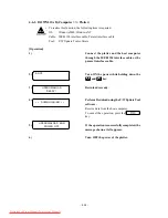
Page 75: ...NTER key 3 If CARTRIDGE has been selected When you press the or key the number of replacements is displayed for each ink cartridge Press the ENTER key to exit from the function If SCAN COUNT has been selected When you press the or key the number of scans is displayed for each ink cartridge Press the ENTER key to exit from the function FUNCTION ADJUST ENT ADJUST REPLACE CNT ent REPLACE CNT CARTRIDG...

Page 76: ...e function If USE TIME has been selected Display the operating time Press the ENTER key to exit from the function The display value is the value accumulated since the power is turned on for the first time Select INK PARAMETER in 4 3 6 Default set to perform initialization REPLACE CNT Pig m2 REPLACE CNT TIME h Downloaded From ManualsPrinter com Manuals ...

Page 77: ...ion 0 Adjusting function CLOSE DISPLAY Operation 1 Select the ADJUSTMENT Press the ENTER key 2 Select the DEFAULT SET pressing the FUNCTION key Press the ENTER key 3 Select the parameter using the or key 4 Press the ENTER key and the parameter settings are reset to the initial values FUNCTION ADJUST ENT ADJUST DEFAULT SET ent DEFAULT SET SET SETUP PRM DEFAULT SET SET INK PRM 1 DEFAULT SET SET INK ...

Page 78: ...alue display when checking the head height 4 Adjust the bottom position using the or key Press the ENTER key 5 Adjust the Cap position using the or key Press the ENTER key 6 Adjust the Cap height using the or key Press the ENTER key 7 Adjust the Wiper position using the or key Press the ENTER key 8 Adjust the Wiper height using the or key When you press the ENTER key the setting is registered and ...

Page 79: ...ress the ENTER key 2 Select the INK SETUP pressing the FUNCTION key Press the ENTER key 3 Adjust the ink type using the or key Adjust the Rear Front using the or key 4 Upon completion of Rear Front Ink type setting press the ENTER key FUNCTION ADJUST ENT ADJUST INK SETUP ent INK SETUP P Pigcm F Pigcm INK SETUP P PigOG F Pigcm INK SETUP P Dye F Pigcm INK SETUP P Sub F Pigcm INK SETUP P Pigcm F PigO...

Page 80: ...entered Use the and keys to move left or right Use the and keys to enter the number Press the ENTER key to finalize the number When the key is pressed the value returns to what it was before the change 4 After the ID numbers of heads 1 to 6 have been entered press the key The values that were input are stored under system parameters and this operation ends Incorrect entry in step 3 results in an e...

Page 81: ...ted should be used the correct adjustment becomes unavailable any longer In this adjustment the actual measured value is entered but the value found from the following formula is stored under the system parameter Adjustment value of the left end 5mm Actual measured value mm stored in increments of 0 1mm Adjustment value of the right end 5mm Actual measured value mm stored in increments of 0 1mm JV...

Page 82: ... measured value of the dead space in units of 0 1 mm using the or key Press the ENTER key to store the entered value 5 The indication given in the step of procedure 3 will be restored on the LCD Press the key to exit from the EDGE ADJUST To clear the adjustment value press the key To draw an adjusting pattern press the key ADJUST EDGE L 10 0 R 10 0 ADJUST CLEAR DRAW ADJUST EDGE CLEAR DRAW Download...

Page 83: ...tion becomes the b position when the distance a a in the above diagram is taken to be 500 mm In this adjustment the actual measurement is entered but the value found from the following formula is stored under the system parameter Adjustment value 500 mm Actual measurement mm stored in units of 0 1 mm Operation 1 Select the ADJUSTMENT Press the ENTER key 2 Select the 500mmSQUARE pressing the FUNCTI...

Page 84: ...measured value for the X and Y directions using the or key Press the ENTER key to store the entered value 5 The indication given in the step of procedure 3 will be restored on the LCD Press the key to exit from the 500mm SQUARE To clear the adjustment value press the key To draw an adjusting pattern press the key 500mm SQUARE X 500 0 Y 500 0 500mm SQUARE CLEAR DRAW 500mm SQUARE CLEAR DRAW Download...

Page 85: ...720 1440 x 1440 4 Select the quality using the or key and then press the ENTER key QUALITY Standard Fine Highspeed 5 Select the number of divisions using the or key and then press the ENTER key PASS 2pass 3pass 4pass 6pass 8pass 12pass 16pass 32pass Some items cannot be selected depending on the resolution 6 Select the high speed scan on off using the or key and then press the ENTER key Some items...

Page 86: ... colorant ink Reason This adjustment changes the reference value for media correction With this change the four types of SET UP MEDIA COMP for the user are all changed and therefore the user needs re adjustment The image shown at left is an image when the circled section above is observed with a scope Make adjustment so that the 2 pass dots are shot between 1 pass dots Good sample Bad sample adjus...

Page 87: ...n value without performing plotting 3 Press the ENTER key to start plotting Press the key to interrupt the operation Select the DPI using the or key 4 Input the correction value the or key Press the ENTER key to store the entered value FUNCTION ADJUST ENT ADJUST MEDIA COMP2 ent MEDIA COMP2 PRINT START ent MEDIA COMP2 Adj Downloaded From ManualsPrinter com Manuals ...

Page 88: ...tion 1 Select the TEST Press the ENTER key 2 Select the CHECK PATTERN pressing the FUNCTION key Press the ENTER key 3 Select a pattern using the and keys Pattern 100 50 25 6 25 NOZZLE COLOR FEED If two or more colors are selected a density pattern is drawn while mixing the se lected colors Note that however nozzle checking patterns are respectively plotted for the selected colors When necessary it...

Page 89: ... ENTER key Drawing way BI D 1 2 3 4 6 8 12 16 32 pass UNI D 1 2 3 4 6 8 12 16 32 pass Some items cannot be selected depending on the resolution 4 Select the plotting length in the XandY direction using the or key and press the ENTER key Length setting 10 mm to the sheet length in increments of 10 mm 5 Select the ink type used for plotting using the or key and press the ENTER key CHK PATTERN PATTER...

Page 90: ...gh speed scan Plotting can be aborted by pressing the key 8 After the completion of the plotting press the key in repetition to return the layers of screens one by one to permit the conditions to be changed CHK PATTERN COLOR KCMY CHK PATTERN PATTERN PLOT b Plotting a nozzle checking pattern 1 Select NOZZLE using the or key and press the ENTER key 2 Select the resolution using the or key and press ...

Page 91: ...ct the color to be used Press the or key tto select wheter the color is drawned or not Press the ENTER key to finalize the number 6 At this time it is now ready for the drawing Press the ENTER key to start drawing When the device is ready for plotting the followings can be setted shift the origin REMOTE LOCAL select the head used and the high speed scan Plotting can be aborted by pressing the key ...

Page 92: ...e items cannot be selected depending on the resolution 4 Select the density using the or key and press the ENTER key Density ALL 100 50 25 At this time it is now ready for the drawing 5 At this time it is now ready for the drawing Press the ENTER key to start drawing When the device is ready for plotting the followings can be setted shift the origin REMOTE LOCAL select the head used and the high s...

Page 93: ...ng way BI D 1 2 3 4 6 8 12 16 32 pass UNI D 1 2 3 4 6 8 12 16 32 pass Some items cannot be selected depending on the resolution 4 Select the interval in the Y direction using the or key and press the ENTER key Length setting 16 dot to 512 dot 6 After the completion of the plotting press the key in repetition to return the layers of screens one by one to permit the conditions to be changed CHK PATT...

Page 94: ... ready for the drawing Press the ENTER key to start drawing When the device is ready for plotting the followings can be setted shift the origin REMOTE LOCAL select the head used and the high speed scan Plotting can be aborted by pressing the key 8 After the completion of the plotting press the key in repetition to return the layers of screens one by one to permit the conditions to be changed CHK P...

Page 95: ...3 Select the plot parameter using the or key System parameter Ink parameter 1 Ink parameter 2 Maintenance parameter Servo parameter Adjustment parameter Information parameter 4 Press the ENTER key to start plotting HEAD ID is issued in the maintenance list at the time of maintenance release FUNCTION TEST ENT TEST PARAM DRAW ent PARAM DRAW DRAW SYSTEM PRM Downloaded From ManualsPrinter com Manuals ...

Page 96: ...t HEAD U Dadjsut PARAMETERadjust2 FAIN FAINAL TEST DRAW Operation 1 Select the TEST Press the ENTER key 2 Select the ALL PATTERN pressing the FUNCTION key Press the ENTER key 3 Press the ENTER key to start plotting FUNCTION TEST ENT TEST ALL PATTERN ent ALL PATTERN PRINT START ent Downloaded From ManualsPrinter com Manuals ...

Page 97: ...unction with ink filled may cause ink leakage from the head Operation 1 Select the TEST Press the ENTER key 2 Select the X SERVO pressing the FUNCTION key Press the ENTER key 3 Press the ENTER key twice without changing the set value Now the screen changes over to permit the setting of a traveling amount in the X direction 4 Press the ENTER key without changing the set value The aging in the X dir...

Page 98: ...lotter can break Operation 1 Select the TEST Press the ENTER key 2 Select the Y SERVO pressing the FUNCTION key Press the ENTER key 3 Press the ENTER key twice without changing the set value Now the screen changes over to permit the setting of a traveling amount in the Y direction 4 Press the ENTER key without changing the set value The aging in the Y direction starts 5 Press the key to interrupt ...

Page 99: ...TEST Press the ENTER key 2 Select the XY SERVO pressing the FUNCTION key Press the ENTER key 3 The screen changes over to permit the setting of speed and acceleration in the X direction Press the ENTER key twice without chang ing the set value 4 The screen changes over to permit the setting of speed and acceleration in the Y direction Press the ENTER key twice without chang ing the set value 5 The...

Page 100: ...n 1 Select the TEST Press the ENTER key 2 Select the ACTION TEST pressing the FUNCTION key Press the ENTER key 3 Select the action item using the ENTER key 4 Execute the action using the or key 5 Press the key to exit from the function FUNCTION TEST ENT TEST ACTION TEST ent ACTION TEST FAN MOTOR LOW ACTION TEST Y CUTTER DOWN ACTION TEST COOLING FAN OFF ACTION TEST ROLL MOTOR OFF Downloaded From Ma...

Page 101: ...on the LCD ON Lever is in its lower position OFF Lever is in its upper position 4 Press the key The state of the rear paper sensor is shown on the LCD ON Medium is present OFF Medium is absent 5 Press the key The state of the Y origin sensor is shown on the LCD ON Origin has been detected OFF Origin has not been detected 6 Press the key The state of the capping sensor is shown on the LCD ON The ca...

Page 102: ...e LCD ON Origin has been detected OFF Origin has not been detected 11 Press the key Current status of ink pack sensor is displayed The color codes of the cartridges that have run out of ink are appear 12 Press the key Current status of ink end sensor is displayed The color codes of the cartridges that have run out of ink are appear Press the key in repetition to return the layers of screens one by...

Page 103: ...ding by the paper sensor is given on the LCD Regarding the use of the paper width sensor refer to 2 3 Brief explanation of media size detection control The head can be moved to a desired position using the or key The number at the left end indicates the readout value of the sensor No media About 600 Clear film About 400 White media 0 to 100 4 Press the key to exit from the function FUNCTION TEST E...

Page 104: ...y shown on the LCD matches the name of the key pressed 4 Press the key to exit from the function FUNCTION TEST ENT TEST KEYBOARD ent KEYBOARD TEST Key NONE KEYBOARD TEST Key REMOTE KEYBOARD TEST Key FUNCTION KEYBOARD TEST Key TESTDRAW KEYBOARD TEST Key CLEANING KEYBOARD TEST Key ENTER KEYBOARD TEST Key CLEAR KEYBOARD TEST Key LEFT KEYBOARD TEST Key RIGHT KEYBOARD TEST Key UP KEYBOARD TEST Key DOWN...

Page 105: ...t is started Press the or key to change the display item Press the or key to change the display language 4 Press the key to exit from the function FUNCTION TEST ENT TEST DISPLAY test ent DISPLAY test LOCAL DISPLAY test mm DISPLAY test JPN REMOTE DISPLAY test JPN DISPLAY test USA DISPLAY test GER DISPLAY test FRA DISPLAY test SOA DISPLAY test ITA DISPLAY test POR Key UP Downloaded From ManualsPrint...

Page 106: ...he TEST Press the ENTER key 2 Select the LCD TEST pressing the FUNCTION key 3 Press the ENTER key This causes the device to start to indicate test patterns on the LCD Displays items at specific intervals 4 Press the key to exit from the function FUNCTION TEST ENT TEST LCD TEST ent Downloaded From ManualsPrinter com Manuals ...

Page 107: ...NTER key 5 Select the number of drive steps 500 16300 CONTINUE using the or key Press the ENTER key 6 Select the driving speed using the or key Press the ENTER key 7 The pump motor starts running After the pump motor performance is checked the head selection can be made If you select the CONTINUE press the ENTER key to exit from the function FUNCTION TEST ENT TEST PUMP MOTOR ent PUMP MOTOR PUMP 1 ...

Page 108: ...r operation in about 7 years Operation 1 Select the TEST Press the ENTER key 2 Select the TIMER CHECK pressing the FUNCTION key 3 Press the ENTER key Displays the present date and time Press the ENTER key to shift to the date setup mode 4 The present date and time is shown on the LCD using the or key 5 Press the key to exit from the function FUNCTION TEST ENT TEST TIMMERcheck ent TIMMERcheck DATE ...

Page 109: ... action to continue Turn the power OFF and then back ON Operation 1 Select the TEST Press the ENTER key 2 Select the MEMORY CHECK pressing the FUNCTION key Press the ENTER key 3 Select the item to be checked using the or key Press the ENTER key and the check menu for memories will be invoked FUNCTION TEST ENT TEST MEMORY check ent MEMORY check CHECK SDRAM MEMORY check CHECK F ROM MEMORY check CHEC...

Page 110: ...er of checks are shown on the LCD Single check takes about 10 minutes When an error arises the error address will appear on the LCD At this time if the key or the key is pressed read write data and number of checks until error occurrence will be displayed 4 Press the key to terminate the SDRAM checking MEMORY check CHECK SDRAM MEMORY check WAIT TIME OFF MEMORY check CNT 1 SDRAM MEMORY check E h ac...

Page 111: ...Y check CHECK F ROM MEMORY check CNT 1 F ROM MEMORY check E h ac 400000 M c S RAM check 1 The indication S RAM is shown on the LCD 2 Press the ENTER key The plotter starts checking The number of checks is shown on the LCD When an error arises the error address and read write datawill appear on the LCD and the checking will be aborted 3 To terminate the S RAM checking turn the power off MEMORY chec...

Page 112: ...gle check takes about 2 minutes When an error arises the error address and read write datawill appear on the LCD and the checking will be aborted 3 Press the key to terminate the I F S RAM checking MEMORY check CHECK I F S RAM MEMORY check CNT 1 I FRAM MEMORY check E 0 0 0 0 0 0 0 0 Downloaded From ManualsPrinter com Manuals ...

Page 113: ...ess the ENTER key 2 Select the SKEW CHECK pressing the FUNCTION key Press the ENTER key 3 Enter the value to feed the paper using the or key 4 Press the ENTER key Press the key to exit from the function FUNCTION TEST ENT TEST SKEW CHECK ent SKEW CHECK FEED m SKEW CHECK FEED m Downloaded From ManualsPrinter com Manuals ...

Page 114: ... or key to display the temperature around each head Temperature around the head and the entered value to change AD Ta1 to Ta6 H1 H2 H6 Temperature of the nozzle and forward voltage drop of diodes Tj1A Tj1B to Tj6B H1A H2B H6B 4 Press the key to exit from the function FUNCTION TEST ENT TEST TEMP CHECK ent TEMP CHECK Ta 1 ο TEMP CHECK Ta 2 ο TEMP CHECK Ta 3 ο TEMP CHECK Ta 4 ο TEMP CHECK T j 1A ο TE...

Page 115: ... is decided 100mm to max movement distance 100mm step 5 Press the ENTER key With F W 1 60 or later the carriage shuttles the set distance 3 times and the linear encoder value and Y motor encoder value are read If the difference between the values before and after movement to the linear encoder exceeds 3 an error results and check is completed Indicate the following values when carriage was returne...

Page 116: ...of capping position before and after that is moved is zero Press the FUNCTION key to display the following values Capping position value before movement resolution Ms value of Y motor encoder 5µm Es value of linear encoder 720dpi Capping position value after movement over the specified distance resolution Mn value of Y motor encoder 5µm En value of linear encoder 720dpi Capping position value afte...

Page 117: ...tion in increments of 0 1 mm in increments of 1 step Adjustment X of the medium cutting position in increments of 0 1 mm Medium edge detection level Unit Distance between head 1 nozzle row A and head 2 nozzle row A Distance between head 1 nozzle row A and head 2 nozzle row A Distance between head 1 nozzle row A and head 2 nozzle row A Distance between head 1 nozzle row A and head 2 nozzle row A Di...

Page 118: ...n Long direction feed rate 1mm s Page length clip 0 The page length command is activated and clipping is done on the page n The page length command is inactivated the plot is plotted and a margin is added at the rear end Initial value for X medium size Unit cm Selects the IEEE1284 receive speed Mechanical size Hash check pass Adjusting function extention Initialization 0 Disabled 1 Enabled Medium ...

Page 119: ...TER key to permit the value to be changed 5 Change the value using the or key 6 Press the ENTER key to store the value 7 Press the key to exit from the function FUNCTION PARAMETER ENT PARAMETER SYSTEN PRM ent SYSTEM PARAMETER 0 0 COMP X SYSTEM PARAMETER 62 0 SUPPORT SYSTEM PARAMETER 62 0 0 SYSTEM PARAMETER 62 0 2 SYSTEM PARAMETER 62 2 SUPPORT Downloaded From ManualsPrinter com Manuals ...

Page 120: ...used in the field Never change the value 4 5 5 SERVO PARAMETER This is not used in the field Never change the value 4 5 6 ADJUSTMENT PARAMETER Parameters are present for each waveform plot The value of each parameter canbe changed and stored automatically through adjustment 4 5 7 INFORMATION PARAMETER This is not used in the field Never change the value Downloaded From ManualsPrinter com Manuals ...

Page 121: ...omputer 4 6 1 UPLOAD Plotter Computer To realize this function the following item is required OS Windows2000 Cable IEEE1394 interface cable Tool F W Update Tool software Operation 1 Connect the plotter and the host computer through the IEEE1394 interface cable 2 Turn ON the power while holding down the and key 3 Upload is ready 4 Perform Upload using the F W Update Tool software Transfer parameter...

Page 122: ...EEE1394 interface cable or the pararel interface cable 2 Turn ON the power while holding down the and key 3 Download is ready 4 Perform Download using the F W Update Tool software Receive data from the host computer To cancel the operation press the key 5 If the operation is successfully completed the message shown at left appears 6 Turn OFF the power of the plotter BOOT UP DOWNLOAD READY DOWNLOAD...

Page 123: ...and error Check wheter interface connection is normal Turn OFF the power and then turn it back ON Parameter error Check wheter the file selected on the host computeer is for JV4 Turn OFF the power and then turn it back ON Data error Check wheter the contents of the file selected on the host computer are normal and not defective Turn OFF the power and then turn it back ON Downloaded From ManualsPri...

Page 124: ...pment Division of MIMAKI contains the following 2 files 1 JV4 ROM This is the F W version updating file 2 FILECHK EXE This program checks for copying mistakes when the F W version updating file is copied to the floppy disc Be sure to check every time the file is copied You may download F W version up file through our Web site on the Internet URL http www mimaki co jp Download one of the following ...

Page 125: ...e file name indicates the version number of F W 1 FWIF L EXE Japanese version for WINDOWS 2 FWIF Z EXE English version for WINDOWS 3 FWIF sea hqx Japanese English shared version for MAC Every file is a self unarchiving compressed file When unarchived the file is extracted to the following three files 1 FWIF ROM This is the F W version updating file 2 README TXT This is the version updating manual ...

Page 126: ...he case of the mechanical side version updating file the at both ends flashes 4 When all the data are received the data is written into the flash ROM 5 Upon completion of the writing the version of the firmware written into the ROM will be shown on the LCD 6 Re turn on the power to the plotter Do not turn the power OFF while the data is written into the flash ROM There is a danger of damaging the ...

Page 127: ...er version updating mode Repeat the version updating from the beginning The received data are not for the interface Check the version updating file Data stored in the ROM could not be erased Replace the main PCB with a new one Data stored in the ROM could not be erased Data could not be written into the ROM Data could not be written into the ROM Data written into the ROM are wrong Data written int...

Page 128: ... item No selective item HEAD 1 HEAD 2 HEAD 3 HEAD 4 HEAD 5 HEAD 6 CLEAR DRAW CLEAR DRAW DPI QUALITY PASS High SPEED No selective item 100 50 25 6 25 NOZZLE COLOR FEED PRN adjust2 HEAD ADJUST WASH SELECT CLEANING REPLACE COUNTER DEFAULT SET INK SETUP CAPPING HEAD ID ADJUST EDGE 500mm SQUARE SET QUALITY MEDIA COMP2 CHK PATTERN 4 8 Maintenance menu tree ADJUST TEST Y Si Y Re Y Bi FINAL Standard Stron...

Page 129: ...t used in the field ADJ PARAMETER Total 25 items This is not used in the field INFO PARAMETER Total 96 items This is not used in the field SYSTEM PRM INK PRM 1 INK PRM 2 MAINTE PRM SERVO PRM ADJUST PRM INFO PRM No selective item No selective item No selective item No selective item FAN MOTOR Y CUTTER COOLING FAN ROLL MOTOR SET LEVER REAR PAPER Y ORIGIN CAPPING STATION WIPER FRONT COVER X ORIGIN IN...

Page 130: ... 4 72 Downloaded From ManualsPrinter com Manuals ...

Page 131: ... 5 1 CHAPTER 5 DISASSEMBLING ASSEMBLING PROCEDURE Downloaded From ManualsPrinter com Manuals ...

Page 132: ...t cover 2 Remove the screw B3 x 6Ni then remove the Y cover 3 Remove the SR cover 4 Remove the screw B3 x 6Ni then remove the YR cover Before removing the YR cover be sure to remove the cable because the cable of the front cover sensor assembly is clamped on the back of the YR cover 5 Remove the screw B4 x 10Ni then remove the right cover Assembling procedure Assembly is reverse of disassembly Dow...

Page 133: ...3x8SMW Ni P3x6SMW P3x8SMW Ni P3x8SMW Ni B3x6Ni B3 x6Ni B3x6Bk B4x6Bk Front cover U Y cover stay Y cover P3x8SMW YR cover Right cover Sub side plate R assy SR cover Under cover U Right side plate SR cover BKT 1 SR cover BKT 2 B4 x10Ni B4x10Ni B3x6Ni Downloaded From ManualsPrinter com Manuals ...

Page 134: ... connected to the IO PCB assembly 3 Remove the screw P3 x 8SMW then remove the IO PCB assy from under flame Assembling procedure Assembly is reverse of disassembly to Fan motor 3 assy to Wiper sensor assy to Under point sensor assy to Paper sensor assy to Clamp sensor assy to Origin sensor assy to Pump motor 1 assy to Pump motor 2 assy to Pump motor 3 assy to Pump motor 4 assy to Station motor ass...

Page 135: ...g on the mounting position 4 Remove the screw B3 x 6Ni then remove the platen cover R 5 Remove the screw P3 x 6Ni then remove the paper sensor R BKT from under flame 6 Remove the screw B3 x 10Bk then remove the paper sensor R assy from the paper sensor R BKT Assembling procedure Assembly is reverse of disassembly to IO PCB assy CN4 B3 x6Ni B3 x6Ni B3 x6Ni B3 x10Bk B3 x6Ni B3 x6Ni Media guide shaft...

Page 136: ... 6SMW from the X motor BKT then remove the X motor assy Adjust Y timing belt Refer to 6 2 5 Adjustment of the X motor belt tension P 6 11 Assembling procedure Assembly is reverse of disassembly to Main PCB assy CN20 to Main PCB assy CN6 7 B3 x10Bk P4 x8SMW P3 x6SMW P4 x8SMW P4 x8SMW P3 x6SMW SSWP4 XM BKT Bearing X Origin sensor assy Pulley stopper SSWP4 TN15 20 Pulley Bushing XM BKT Bearing Left s...

Page 137: ...isassemble Do not remove the X pulley because it is positioned precisely Do not loosen the set screws SSWP4 X 4 Do not loosen the set screws SSWP3 X 3 because the two protruded rollers are positioned precisely Downloaded From ManualsPrinter com Manuals ...

Page 138: ... x 6Bk P4 x 8SMW then remove the head cover assy and the head UD BKT assy 2 Remove the left cover loosen the tension screw until there is no tension then remove the Y tension pulley assy 3 Remove the screw P4 x 2SMW on the slider from belt holder then pull the belt holder assy 4 Remove the Y timing long belt assy from the Y bar and then replace it Follow the procedure given below to replace the Y ...

Page 139: ... supply switch remove the front cover and the Y cover 3 Remove the screw B3 x 6Bk then remove the head cover 4 Remove the screw P3 x 6SMW then remove the FPC cover 5 Remove all of the harnesses on the slider PCB 6 Remove all of the spacers SQ 25 that hold the slider PCB 7 Replace the slider PCB Assembling procedure Assembly is reverse of disassembly to HDC 4Head PCB assy CN2 6 to HDC 2Head PCB ass...

Page 140: ...ll the Y timing long belt assy from the Y bar and replace it Follow the procedure given below to replace the linear encoder PCB scale After replacing the linear encoder PCB scale be careful not to contact the linear encoder PCB scale Refer to the adjustment items 1 Remove the YR cover and the YL cover 2 Remove the screw B3 x 6Ni then remove the scale spring on on the left side of the Y bar 3 Remov...

Page 141: ...he linear scale is positioned approximately at the center of the sensor s recessed section but does not contact the wall Linear encoder Linear scale Front view Side view Optical axis Optical axis P3 x6SMW B3 x6SMW P3 x6SMW CS3 x8SMW P2 x12 CS3 x8SMW B3 x6Ni Scale hook Scale holder Shaft holder SS flat 3 Shaft holder Slider L sensor BKT Linear encoder scale assy Slider stopper L Slider PCB BKT H ax...

Page 142: ...e power supply switch remove the front cover the Y cover and the head cover 5 Remove the screw P3 x 6SMW and then remove the head cover BKT 6 Remove the screw P3 x 6SMW and then remove the damper holder 7 Remove the damper assy of the print head to replace 8 Remove the screw P2 x 8SMW from the print head assy to replace 9 Remove the screw B3x 10Bk from the angle spring and remove it 9 Pull out the...

Page 143: ...SMW Head bracket P4 x 12SMW B3 x 10Bk Angle spring Adjusing spring Adjusing spring Head adjusing screw Adjusing spring Adjuster Head adjusing screw Head adjusing screw B3 x 10Bk Adjuster Angle spring Print head P2 x 8SMW Damper holder Downloaded From ManualsPrinter com Manuals ...

Page 144: ...move the screw P3 x 6SMW and then remove the FPC cover Pull out it from the slider PCB 5 Remove the electrical unit cover and then pull out the main FPC cable from HDC PCB HDC upside 5 downside 2 6 Remove the screw P3 x 6SMW and then remove the FPC ground board and the FPC holder 7 Remove the screw P3 x 6SMW to remove the FPC guide plate from the slider PCB BKT and then remove the cable clamp 8 Re...

Page 145: ...y 6 Remove the screw B3 x 6Bk for mountaing the cutter solenoid assy 7 Pull down the cutter solenoid assy and replace it Follow the procedure given below to replace the paper width sensor PCB assy 1 Remove the the paper width sensor assy from the cutter BKT Only the one fixed by the notch of sensor Assembling procedure Assembly is reverse of disassembly to Slider PCB assy CN32 to Slider PCB assy C...

Page 146: ...er to the center of the platen using the JOG key 2 Turn OFF the power supply switch remove the SR cover the YR cover 3 Remove the screw TP3 x 12F and then remove the cap housing U After removing the screw you can remove cap housing U by pressing the fitting notch using a slotted screwdriver 4 Disconnect the tube black and pump tube white of the Cap assy removed 5 Remove the cap assy and replace it...

Page 147: ...sensor assy 3 Remove the screw P3 x 6SMW and the D point sensor BKT together with sensor 4 Remove the station sensor from the D point sensor BKT and replace it Capping sensor assy When attaching the capping sensor assy press it until the notch fits into place 1 Turn ON the power of the device and then move the slider to the center of the platen using the JOG key 2 Turn OFF the power supply switch ...

Page 148: ...onnected to the wiper sensor assy 4 Remove the screw P3 x 6SMW and the wiper sensor BKT together with sensor 5 Remove the wiper sensor from the wiper sensor BKT and replace it Assembling procedure Assembly is reverse of disassembly P3 x 6SMW P3 x 6SMW P3 x 6SMW Wiper motor bracket S Station motor gear Wiper motor assy SSWP3 x 3 Wiper gear S Wiper gear S E ring Belt Wiper bracket S Wiper sensor bra...

Page 149: ...e the main PCB Follow the procedure given below to replace the power PCB 1 Remove the screw B3 x 6Bk P3 x 6SMW and remove the main PCB BKT 2 Remove all of the cables connected to the power PCB 3 Remove the screw P3 x 8SMW and remove the poser PCB to Cover sensor assy to Maintenance cover sensor assy to Y axis motor assy to Y axis motor assy to X motor junction cable assy to X motor junction cable ...

Page 150: ...e all of the cables connected to the HDC 2 Head PCB assy 3 Remove the screw SQ 60 and remove the HDC 2 Head PCB assy Assembling procedure Assembly is reverse of disassembly to Main PCB assy CN19 to Main PCB assy CN1 to Power switch To Main PCB assy PN18 Cartridge cover R HDC 4Head PCB assy Main FPC1 assy P3 x8SMW Spacer Main FPC2 assy DC cable assy Cooling fan motor assy HDC FPC assy Nut FG cable ...

Page 151: ...remove the front cover the Y cover and the head cover 3 Pull the ink damper for replaced tube from the head 4 Loosen the screw and then send back the ink inside the tube to the cartridge 5 Remove the screw B3 x 6Bk and then remove the bear cover L R and remove the screw for the ink supply tube ø2 ø3 6 Pull the ink supply tube to replace from the cable bear and replace it Assembling procedure Assem...

Page 152: ... 5 22 Downloaded From ManualsPrinter com Manuals ...

Page 153: ... 6 1 CHAPTER 6 ADJUSTMENT Downloaded From ManualsPrinter com Manuals ...

Page 154: ... 6 2 6 1 Adjusting item list Downloaded From ManualsPrinter com Manuals ...

Page 155: ... 2 for M3 to M5 Adjusting procedure 1 Loosen a screw on the cutter assy for the slider 2 Move the Cutter assy up and down so that the gap between the cutting edge and platen becomes 1 5 to 2mm 3 Loosen a screw on the cutter assy After cutter height adjustment alwais perform the adjustment of the edge Cutter assy mounting screw 1 5mm to 2mm Downloaded From ManualsPrinter com Manuals ...

Page 156: ... Wiping Y Wiping height 3 Adjustment of the station position Although the operation adjustment is serialized correct adjustment values are written to parameters only if the operation adjustment is performed through to the end Therefore be sure to make adjustment through to the end In operation adjustment set the head height to the bottom position 1 Assembling adjustment forward and backward positi...

Page 157: ...sition of Cap adjustment value 250 to 380 If the Cap is removed check the station sensor and station belt cam phase 2 Cap Y 3 Capping height adjustment value 1 0 to 2 2 If the Cap is removed check the station sensor and station belt 4 Wiping Y 5 Wiping height adjustment value 3 2 to 4 2 1 Bottom point of Cap Adjust the bottom position of Cap using the or key ADJUST LOWER POS ADJUST CAP POS ADJUST ...

Page 158: ... height at which the Cap contacts the head using the or key 4 Wiping Y Adjust Wiping Y so that the center of the wiper agrees with the center of the head using the or key Front view enlarged Press the key to move the wiper back and forth The section below the taper section of the Cap is hidden Downloaded From ManualsPrinter com Manuals ...

Page 159: ...ead using the or key 3 Station position check 1 With the power of the device turned ON set an appropriate media and then move the head on the platen using the JOG key 2 Place plain paper 180x70mm on the Cap assy Press the key to move the wiper back and forth Downloaded From ManualsPrinter com Manuals ...

Page 160: ...ly 4 Press the plain paper with your hand to make a mark of the Cap and then remove it If the gap between the Cap and flashing is 0 5mm or more the result is OK otherwise re adjust the forward and backward position of the Cap 0 5mm or more 0 5mm or more 1 Return the head to on cap 2 Flashing 3 Move the head on platen Downloaded From ManualsPrinter com Manuals ...

Page 161: ...coder scale has been replaced Tools to be used Phillips screwdriver No 2 for M3 to M5 Adjusting procedure 1 Loosen the screws in the X motor bracket 2 Within the movable range of the slider move the assy up and down so that the gap between the linear encoder scale and linear sensor PCB is about 1mm 0 5mm Linear sensor PCB assy Mounting screw Downloaded From ManualsPrinter com Manuals ...

Page 162: ...5 Tension gauge Max 300gf or more Scale L 150 Adjusting procedure 1 Loosen the screw in the Y motor total assy 2 Adjust the Y motor total assy position so that when the middle of the timing belt is pressed down with 300gf it bends between 1 2mm and 1 5mm then fix in the place 300 gf Bending amount 1 2mm to 1 5mm Y motor total assy mounting screw Downloaded From ManualsPrinter com Manuals ...

Page 163: ... to M5 Tension gauge Max 300gf or more Scale L 150 Adjusting procedure 1 Loosen the screw in the X motor total assy 2 Adjust the Y motor total assy position so that when the middle of the timing belt is pressed down with 300gf it bends between 1 2mm and 1 5mm then fix in the place 300 gf Bending amount 2mm to 2 5mm X motor BKT mounting screw Downloaded From ManualsPrinter com Manuals ...

Page 164: ...d Magnifier Magnification of approx 50 Adjusting procedure Make adjustment in the following order with the head lowered to the bottom position Follow the steps below 1 Adjustment of the head angle SLANT adjust for each head six positions 2 Adjustment of the head angle REAR FRONT adjust for each head three positions 3 Adjustment of the dot position PRINT adjust2 operation adjustment 1 Adjustment of...

Page 165: ...nd then turn the tilt adjustment screw according to the tilt direction As a rough standard the head tilts 50µm for each screw rotation Care is required when using a magnifying glass because of horizontal and vertical inversion 1 Good condition Tilt adjuster Tilt adjustment screw Mounting Screws Head 1 or 2 Head 3 or 4 Head 5 or 6 1scan 2scan 3scan 4scan Downloaded From ManualsPrinter com Manuals ...

Page 166: ...lock including the replaced head 2 Turn the forward and backward position adjustment screw according to the overlapping condition of the FRONT and REAR heads Move the REAR side to match the FRONT side or fixed side As a rough standard the head moves 50µm for each screw rotation Forward and backward position mounting screw Forward and backward position adjustment screw REAR Head FRONT Head Download...

Page 167: ...condition 2 Bad condition Turn the screw clockwise 3 Bad condition Turn the screw counterclockwise REAR Head FRONT Head REAR Head FRONT Head REAR Head FRONT Head 141µm 10 m Downloaded From ManualsPrinter com Manuals ...

Page 168: ... 6 16 Downloaded From ManualsPrinter com Manuals ...

Page 169: ...Downloaded From ManualsPrinter com Manuals ...
Page 170: ...D500175 1 00 26102001 MIMAKI ENGINEERING CO LTD 2001 Downloaded From ManualsPrinter com Manuals ...
Reviews: