– 4.24 –
3)
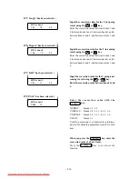
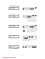
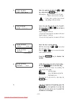
Plot the adjusting pattern using the
key.
Clear the adjustment value using the
key.
Press the
or
key to enter a correction
value without performing plotting.
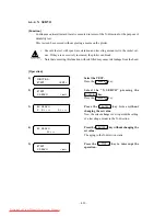
After the completion of plotting, enter a correction
value.
4)
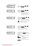
Enter the measured value of the dead space in
units of 0.1 mm, using the
or
key.
Press the
ENTER
key to store the entered
value.
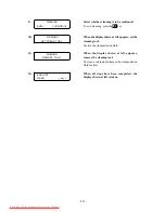
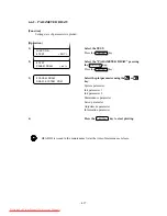
5)
The indication given in the step of procedure
3) will be restored on the LCD.
Press the
key to exit from the “EDGE
ADJUST.”
To clear the adjustment value, press the
key.
To draw an adjusting pattern, press the
key.
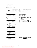
# ADJUST EDGE
L = 10.0
R = 10.0
# ADJUST
CLEAR <
> DRAW
# ADJUST EDGE
CLEAR <
> DRAW
Downloaded From ManualsPrinter.com Manuals
Summary of Contents for JV4-130
Page 2: ...Downloaded From ManualsPrinter com Manuals ...
Page 8: ... vi Downloaded From ManualsPrinter com Manuals ...
Page 9: ... 1 1 CHAPTER 1 OVERVIEW OF MAINTENANCE Downloaded From ManualsPrinter com Manuals ...
Page 18: ... 1 10 Downloaded From ManualsPrinter com Manuals ...
Page 19: ... 2 1 CHAPTER 2 EXPLANATION OF OPERATION Downloaded From ManualsPrinter com Manuals ...
Page 23: ... 2 5 Main PCB block diagram Downloaded From ManualsPrinter com Manuals ...
Page 38: ... 2 20 Downloaded From ManualsPrinter com Manuals ...
Page 59: ... 4 1 CHAPTER 4 MAINTENANCE MODE Downloaded From ManualsPrinter com Manuals ...
Page 130: ... 4 72 Downloaded From ManualsPrinter com Manuals ...
Page 131: ... 5 1 CHAPTER 5 DISASSEMBLING ASSEMBLING PROCEDURE Downloaded From ManualsPrinter com Manuals ...
Page 152: ... 5 22 Downloaded From ManualsPrinter com Manuals ...
Page 153: ... 6 1 CHAPTER 6 ADJUSTMENT Downloaded From ManualsPrinter com Manuals ...
Page 154: ... 6 2 6 1 Adjusting item list Downloaded From ManualsPrinter com Manuals ...
Page 168: ... 6 16 Downloaded From ManualsPrinter com Manuals ...

