background image

1-17

1

Before Use

3

4

5

6

Media

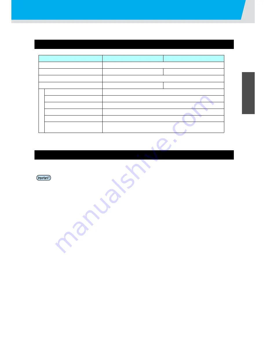
Usable media sizes and notes for handling are described.

Usable sizes of media

Caution in handling of medias

Pay attention to the followings for handling of medias.

Model

JV400-130SUV

JV400-160SUV

Type of Recommended media

Tarpaulin/Weatherproof PVC/FF

Maximum width

1371mm

1620mm

Minimum width

210mm

Maximum printing width

1361mm

1610mm

Ro

ll medi

a

Thickness

0.2mm or less

Roll outside diameter

φ

180mm and less

Roll weight

25kg and less

Roll inside diameter

3 or 2 inches

Side printed

Side facing outward

Roll end treatment

The roll end is gently fixed to the core with weak-adhesive tape or weak
glue for easy removal.

When handling media, wear the gloves.

If you touch the media with your bare hand, the media may be stained due to fingerprints or oil of your 
finger. Be careful about it.

Do not leave the media with the heater ON for a long time.

Waviness may occur on the media and it may cause media clogging.

Use media recommended by MIMAKI to ensure reliable, high-quality printing.

Set the heater temperature to meet the characteristics of the media.

Set the temperature of the Pre-heater, Print heater and Post-heater according to the type and 
characteristics of the media used.

Automatic temperature setting can be made on the operation panel by setting the profile on the 
dedicated RIP. For setting on the RIP, refer to the instruction manual for your RIP.

Pay attention to the expansion and contraction of the media.

Do not use media immediately after unpacking. The media can be affected by the room temperature 
and humidity, and thus it may expand and contract.
The media have to be left in the atmosphere in which they are to be used for 30 minutes or more after 
unpacked.

Do not use curled media.

This may result in paper jamming.
If a regular-sized coated sheet of media is rolled and stored, the coated side has to face outside.

Be careful to dusts on the edge face of the medium.

Some rolls have dusts contained in the package gathered on the edge surface of the roll. If you use as 
it is, the drawing quality may be degraded due to nozzle missing or ink drops. Be sure to set the roll 
after removing dusts adhering on the edge face of the roll.

Summary of Contents for JV400-130SUV

Page 1: ...MIMAKI ENGINEERING CO LTD URL http eng mimaki co jp D202394 17 Original instructions ...

Page 2: ...Panel 1 6 Heater 1 7 Media sensor 1 7 Carriage 1 8 Cutter blade and slot for cutting 1 8 Capping station 1 9 Pinch rollers and Feed rollers 1 9 Connecting Cables 1 10 Connecting USB2 0 Interface Cable 1 10 Connecting the power cable 1 11 Inserting ink cartridges 1 12 Caution in handling of ink cartridges 1 14 How to assemble ink cartridge 1 15 Media 1 17 Usable sizes of media 1 17 Caution in handl...

Page 3: ...nting has been completed 2 25 Cutting a media 2 27 Chapter 3 Extended Functions List of Functions 3 2 Setting Logical Seek 3 3 Setting Drying Time 3 5 Setting Margins 3 6 Perform setting to reduce stripes between passes 3 7 Setting Auto Cleaning 3 8 Setting nozzle face cleaning time 3 9 Other Settings 3 10 Machine Settings 3 11 Setting a AUTO Power off 3 13 Setting the Display of Media Residual 3 ...

Page 4: ...can not be improved 4 28 Automatic Maintenance Function 4 31 Setting the Refreshing Intervals 4 31 Setting the Cleaning Intervals 4 32 Setting the Disway wash Intervals 4 33 Replacing consumables 4 34 Replacing the wiper 4 34 If a Waste Ink Tank Confirmation Message Appears 4 35 Replacing the waste ink tank before the waste ink tank confirmation message is displayed 4 38 Replacing the Cutter Blade...

Page 5: ...12 Error messages 5 15 Chapter 6 Appendix Specifications 6 2 Machine specifications 6 2 Ink specifications 6 3 Setting orders depending on ink type 6 4 Setting orders of ink cartridges 6 4 Sheet for inquiry 6 5 Warning labels 6 6 Function Flowchart 6 8 ...

Page 6: ...radio frequency energy and if not installed and used in accordance with the Operation manual may cause harmful interference to radio communications Operation of this equipment in a residential area is likely to cause harmful interference in which case the user will be required to correct the interference at his own expense In the case where MIMAKI recommended cable is not used for connection of th...

Page 7: ...alled as this machine hereafter Read this Operation manual carefully and understand them thoroughly to use It is also necessary to keep this Operation manual on hand This Operation manual has been carefully prepared for your easy understanding however please do not hesitate to contact a distributor in your district or our office if you have any inquiry Descriptions contained in this Operation manu...

Page 8: ...he symbol indicates that the action shown must be taken without fail or the instructions must be observed without fail A sign representing a particular instruction the sign shown at left instructs to unplug the cable from the wall outlet is shown in the circle WARNING Do not use the machine in a poorly ventilated room or a closed room Use the attached power cable Take care not to damage break or w...

Page 9: ...as soon as possible When the machine is to be moved wait until the heater temperature drops adequately As a criterion wait at least 30 minutes after you turn off the power to the heater Moving the machine must be limited to on the same floor where there is no steps When the machine is to be moved to any place other than on the same step free floor contact your distributor or a sales office of MIMA...

Page 10: ...int circuit board Waste ink is equivalent to waste oil of industrial waste Request an industrial waste disposal company for disposal of waste ink Never open the front cover or raise the lever during printing Opening the cover or raising the lever will abort printing Handling of media Use media recommended by MIMAKI to ensure reliable high quality printing Set the heater temperature to meet the cha...

Page 11: ...o responsibility for any troubles caused through the use of a UV devices not recommended by Mimaki Touching hot parts such as the UV irradiation device with combustible materials may cause firing and or smoking Leaving combustible materials under the UV irradiation device for a couple minutes may also cause firing and or smoking Notes on maintenance It is strongly recommended to use the machine in...

Page 12: ...cle parts in the figure below CAUTION A place exposed to direct sunlight On an inclined surface A place where temperature or humidity varies significantly Use the machine under the following environmental conditions Operating environment 20 to 30 C 68 to 95 F 35 to 65 Rh A place that vibrates A place exposed to direct air flow from an air conditioner or the like Around a place where fire is used ...

Page 13: ... 4 Rear Side and Right Side of the Machine 1 5 Operation Panel 1 6 Heater 1 7 Media sensor 1 7 Carriage 1 8 Cutter blade and slot for cutting 1 8 Capping station 1 9 Pinch rollers and Feed rollers 1 9 Connecting Cables 1 10 Connecting USB2 0 Interface Cable 1 10 Connecting the power cable 1 11 Inserting ink cartridges 1 12 Caution in handling of ink cartridges 1 14 How to assemble ink cartridge 1 ...

Page 14: ...ing Environmental Temperature Use this machine in an environment of 20 to 30 C to ensure reliable printing The heater temperature may not reach the set value depending on the ambient temperature Model Width Depth Height Gross weight JV400 130SUV 2634mm 861mm 1435mm 212kg JV400 160SUV 2879mm 861mm 1435mm 250kg JV400 130SUV 3634 mm or more JV400 160SUV 3879 mm or more 500 mm or more 500 mm or more 1...

Page 15: ...le or more Do not push the cover to move this machine since the cover may be broken 3 Lock the caster When the machine is moved to any place other than on the same step free floor contact your distributor or our service office If you move it by yourself failure or damage may occur Be sure to request your distributor or our service office to move this machine When moving this machine take care that...

Page 16: ...ter Post heater Fixes and dries the ink on the currently produced print Located inside the platen Electrostatic sheet Prevents the media from sticking to the platen due to static Ink cartridges Each cartridge contains an ink of a particular color Cartridge protection cover This prevents an injury or breakage of the machine due to a protrusion of the 600 cc cartridge It is located under the ink car...

Page 17: ...to the paper core right and left of a narrow roll medium less than 1 6m hold the medium It supports the paper USB 2 0 connector This is USB2 0 interface connector Clamp lever rear Interlocks with the clamp lever in the font of this machine LAN connector Please use this connector when you use event mail function Main power switch Turns on off the main power for this machine Leave the main power tur...

Page 18: ...the last input value as the setting value or goes to the immediate lower level of the hierarchy key Use this key on cutting key Draws test patterns to check if there are any drawing failures such as ink clogging Or executes Head cleaning at ink clogging key Use this key to set the temperatures of the Pre heater Print heater and Post heater or check the current temperature of the platen key Perform...

Page 19: ...ater is on the platen is very hot When the front cover is to be opened or media is to be replaced lower the heater temperatures and wait until the platen temperature drops otherwise you can get burned When the media is to be replaced with a thin one lower the heater temperatures and wait until the platen temperature drops adequately Setting a thin sheet of media while the platen is hot may cause t...

Page 20: ...ges according to the thickness of media P 2 5 Cutter blade and slot for cutting The carriage is provided with a cutter unit for cutting off the media that has been printed on The cutter cuts off the sheet of media along the slot for cutting on the platen The cutter blade is consumables If it gets dull replace it with new one P 4 39 Carriage Cutter unit slot for cutting Cutter blade ...

Page 21: ... a new one P 4 34 Pinch rollers and Feed rollers This machine retains the media with the pinch rollers and feed rollers During printing operation the feed rollers feed the media forward Be sure to wear the attached goggles in cleaning within the capping station to protect your eyes against ink Otherwise you may get ink in your eyes Keep the pinch rollers lifted up when this machine is not in use I...

Page 22: ... USB 2 0 repeater cables available on the market Notes on peripheral devices in USB high speed mode When a peripheral device USB memory or USB HDD to be operated in USB high speed mode is connected to the same personal computer that a JV400 machine is connected to the USB device may not be recognized When JV400 is connected to the personal computer to which an external HDD is connected via USB the...

Page 23: ...d disk before outputting it for printing Connecting the power cable 1 Insert the power cable into an inlet of the machine 2 Secure a cable band Secure the cable with the cable band attached to this machine 3 Insert the power plug into a plug socket Do not use any power cables other than the attached power cable Be sure to connect the power cable to the outlet near this machine and make sure that t...

Page 24: ...on the display When INK END is displayed 1 Pull out an ink cartridge to be replaced 2 Insert a new ink cartridge paying attention to the direction of IC chip When INK NEAR END is displayed There is a little of ink left It is recommended to replace the ink cartridge soon since ink may become empty in printing while printing is continuously enabled When you press the key in LOCAL you can check the c...

Page 25: ...ED blinks Expiration 1M is displayed in LOCAL July Unusable LED blinks quickly Expiration 2M is displayed in LOCAL About cartridge ink end and ink near end When ink near end less ink occurs LED red blinks to inform you of it It is recommended to replace it as soon as possible When ink end no ink occurs LED red is lit to inform you of it Replace the ink cartridge Condition of Lamp Description Upper...

Page 26: ... is moved from a cold place to a warm place leave it in the room temperature for three hours or more before using it Make sure to store ink cartridges in a cool and dark place Store ink cartridges and waste ink tank in a place that is out of the reach of children Request an industrial waste processor for processing of empty ink cartridges Do not shake ink cartridges violently This may result in in...

Page 27: ...the side without attaching part of IC chip comes off 2 Raise the cover as described in the photo At this time the claw on the IC chip side does not come off Do not raise the cover forcedly so that you may not damage the claw 3 Remove the remaining claw while pressing the cover as indicated in the photo and remove the cover 2 Set the ink pack on the eco case 1 Turn the side with double coated tape ...

Page 28: ...the case 5 Attach the IC chip Attach the IC chip as indicated in the photo Attach it so that there is no gap in the part indicated with an arrow Bad example of attaching IC chip Fix the ink pack so that it may not be biased in the eco case Good example The corner of the case matches the ink pack corner The ink pack has gone too far downward The ink pack goes slack in spots Bad example No gap shall...

Page 29: ...liable high quality printing Set the heater temperature to meet the characteristics of the media Set the temperature of the Pre heater Print heater and Post heater according to the type and characteristics of the media used Automatic temperature setting can be made on the operation panel by setting the profile on the dedicated RIP For setting on the RIP refer to the instruction manual for your RIP...

Page 30: ...ix the electrostatic sheet Hang the claw of the antistatic sheet on the groove of the platen Remove the electrostatic sheet Remove it in the reverse procedures of assembling and use it with pasted on the magnet of the back side of the UV lamp unit If you removed the antistatic sheet attach the sheet holder on the platen 130SUV three positions 160SUV four positions If you do not attach the sheet ho...

Page 31: ...emperature Settings for the Heaters 2 14 Checking the Heater Temperature 2 15 Test Feeding 2 16 Test Printing 2 17 Test Printing 2 18 Head Cleaning 2 19 About head cleaning 2 19 Perform head cleaning depending on the test printing result 2 19 Set the media feeding 2 20 Setting Feed Correction 2 20 Correct the ink drop position for bidirectional printing 2 22 Printing Data 2 24 Starting a Printing ...

Page 32: ...r ON OFF P 2 3 Referring to Setting a Media P 2 5 Referring to Preparing for the Heaters P 2 14 Referring to Test Printing P 2 17 Referring to Set the media feeding P 2 20 6 7 Correct the ink drop position for bidirectional printing Printing Data Referring to Correct the ink drop position for bidirectional printing P 2 22 Referring to Printing Data P 2 24 ...

Page 33: ...to the I side 2 Turn the power switch ON Push the power switch located on the operation panel The firmware version is displayed when the power is turned ON The machine performs its initial operation 3 The machine enters LOCAL 4 Turn ON the power of the connected PC Turn the power ON after the front cover and maintenance cover are closed Use the machine with always turning ON the main power The fun...

Page 34: ...re adjusting function operate When the main power switch has been turned OFF the auto maintenance functions such as flushing do not operate and this may cause nozzle clogging Keep the front cover and the maintenance cover closed If the cover is opened the auto maintenance function such as the flushing function does not work Turn the power OFF after having checked the position of the head If the po...

Page 35: ...ews rotating each by one turn of a standard screwdriver 3 Rotating the lever of the right side of the carriage Turn the lever left towards you to lower the carriage and turn the lever right towards the back to raise it Perform this work after turning OFF the heater and the temperature becomes low enough Adjust the head height prior to setting the media If the head height is adjusted after the medi...

Page 36: ...en the screw securely 5 Return the carriage to the station position When the power supply is off return the carriage to the station manually When the power supply is on press the key if the screen below is displayed 6 Close the front cover Fix the carriage STAT I ON COMP L ETED ENT ...

Page 37: ...stopper arm works with the clamp lever Do not push the clamp lever down while roll stopper is caught between the roll stopper arm and this machine The roll stopper arm might be broken and roll stopper function 1 might be disabled 1 The function that once pulled out a certain amount of media media pullout is temporarily locked OK NoGood Roll stopper arm Roll holder Device side Roll stopper Roll sto...

Page 38: ...de than Roll holder fixing screw Roll holder Roll Holder Set Position 3 Inch Roll Media 2 Inch Roll Media Roll holder Basis Setting position of 3inch tube Setting position of 2inch tube Roll Holder Side The back of this machine Roll Holder Set Position 3 Inch Roll Media 2 Inch Roll Media Set the base position of roll holder within this range 1 There are two types of the internal diameter of the ro...

Page 39: ...inst the core of the roll media the feeding media may be loosened and thereby the media reaches to the floor P 5 11 7 Tighten the screw of the roll holder 8 Raise the clamp lever in the front of this machine 9 Insert the roll media in this machine The roll media can be smoothly inserted by slanting the media 1 Pull the media out of the roll to the head of the platen 2 Insert the media between the ...

Page 40: ...the right end pinch roller to the right side When using a thick media remove the media press from the media before printing When setting a medium be sure to cover the medium sensors located on the rear of the platen The media cannot be detected unless it is placed over the sensor In case that you use 240mm wide media media cannot be detected if it is set in accordance with Set media approximately ...

Page 41: ...mount is displayed after detecting the media width P 2 12 16 Fix the media on the take up device P 2 12 1 Feed the media up to the core of the roll media of the take up device by pressing the key Check the media end is not caught into the slot on the post heater and then feed the media 2 Fix the middle of the media with adhesive tape 3 In the same manner fix the left side and right side of the med...

Page 42: ...rinted side facing out Setting the torque limiter The take up device is provided with a torque limiter The take up torque can be adjusted with the torque limiter The torque limiter is set at the maximum value when shipped from the factory If the tension is too strong to use a thin sheet of media lower the take up torque with the torque limiter Clockwise turn Increases torque a heavy and thicker me...

Page 43: ... media cutting 3 After determining the origin press the key The printing origin is changed Typical setting position of printing origin The printing origin in the depth direction X is positioned at about 75 mm rearward from the slot for cutting on the platen The printing origin in the scanning direction Y is positioned at 15 mm from the right end of the media The value in the scanning direction Y c...

Page 44: ...o end the setting You can change the temperature set here also in HEATER of the SETUP menu P 3 2 The Heater temperature is controllable at the RIP side if the RIP in use has a function controllable For the setting procedures refer to the instruction manual of the RIP in use Depending on the power supply voltage amount of heat generation differs For the power supply voltage of 100V to 120V it may n...

Page 45: ... 4 5 6 Preparing for the Heaters Checking the Heater Temperature 1 Press the key The current heater temperature is displayed 2 Press the key at the end of confirmation The screen returns to LOCAL PRE PRT POST 3 5 C 4 0 C 5 0 C ...

Page 46: ...ing 8 Press the key The feeding operation is continued until you press the key Feed it to some extent and check the feeding status and then press the key to terminate When setting ON rewind the roll media to take up the slack before printing When Manual Drying Feed is operated select ON P 2 26 For manual Drying Feed when you open the shading cover while the UV lamp lights the UV lamp is turned off...

Page 47: ...p between head row and test pattern The relations between head row and test pattern print position are as follow Note on test printing When using a roll medium rewind the medium by hand before printing so that it is not loose When the roll medium has not been rewound tightly it may cause image quality to deteriorate Pattern of head 1 Pattern of head 2 Head 1 Head 2 Media advance direction ...

Page 48: ... end the operation When the result is abnormal perform head cleaning P 2 19 Prepare the media 250mm wide and 350mm or longer length for printing test patterns Check before test printing If a media has been set P 2 5 If the origin position has been set If the head height has been adjusted P 2 5 When using the nozzle recovery function P 4 28 if the feed corrections do not match printing is done with...

Page 49: ...missing NORMAL When any line is missing when colors are mixed HARD When poor image quality cannot be improved even by NORMAL or SOFT cleaning 3 Press the key 4 Press to select a head to cleaning Set Value 12 Cleaning both heads 1_ Cleaning Head 1 only _2 Cleaning Head 2 only 5 Press the key On completion of cleaning the screen returns to step1 6 Perform test printing again and check the result Rep...

Page 50: ...ending on the status When you have changed the temperature of the heaters make sure that the CONSTANT lamp lights up and that the preset temperature is reached and then start the correction When using a roll medium rewind the medium by hand before printing so that it is not loose When the roll medium has not been rewound tightly it may cause image quality to deteriorate When printing with a take u...

Page 51: ...ing A media feeding rate can be corrected even in the remote mode or when image data is printed 1 Press the key in the Remote 2 Press to enter a corrected feeding rate Corrected feeding rate 255 to 255 The value entered here is reflected in the corrected feeding rate soon 3 Press the key The changed value is registered When you press the key instead of the key the value entered here will be invali...

Page 52: ...nted The printed patterns are called Pattern 1 Pattern 2 Pattern 3 in the order of printing 7 Press to correct the dot position of Pattern 1 Corrected feeding rate 40 0 to 40 0 Check the test patterns The position where an outward feeding line and a return feeding line become one straight line is the correction value When the correction value in not between 40 0 and 40 0 adjust the height of the p...

Page 53: ...ess the key several times to end the setting Performing to correct the dot position without key You can select DROP POScorrect by using the key in the Local without pressing the key Press the key in Local Press to select SETUP and press the key Press to select DROP POScorrect and press the key twice It becomes the same condition as the key is pressed from Local ...

Page 54: ...d of data transmission see the instruction manual for the output software 5 Start printing When using a roll media rewind the media by hand before printing so that it is not loose When the roll media has not been rewound tightly it may cause the image quality to deteriorate It takes 30 seconds to light up the UV lamp if you open the shading cover during printing the printing operation is terminate...

Page 55: ...to the local mode Behavior after printing has been completed Drying Feed When printing has been completed the feeding operation is performed to cure the printed surface with the UV lamp Perform the feeding operation until the back edge of printing passes the UV lamp unit When you press the key the operation is terminated When the machine has been received next data continuously it will operate aft...

Page 56: ...ct ON 6 Press the key 7 Press the key After the heater and the UV lamp are ready start test feeding 8 Press the key The feeding operation is continued until you press the key Feed it to some extent and check the curing status and then press the key to terminate When setting ON rewind the roll media to take up the slack before printing TEST FEED ENT BACKWARD FEED ON BACKWARD FEED ON UV L AMP OF F U...

Page 57: ...ailable to cut the media after printing is completed as follows 1 Press the key 2 Press the key 3 Press to specify the cutting position 4 Press the key The media is cut When the cutting has been completed the current mode returns to LOCAL Screen display during heater cooling down Screen display during heater on standby When a media is cut be careful that the printed side does not touch the floor o...

Page 58: ...2 28 ...

Page 59: ...ettings 3 10 Machine Settings 3 11 Setting a AUTO Power off 3 13 Setting the Display of Media Residual 3 14 Adjusting the Remaining Amount in the Ink Cartridge 3 17 Setting Time 3 22 Setting Units 3 23 Setting a KEY BUZZER 3 24 Set the network 3 25 Setting event mail function 3 27 Setting a LANGUAGE 3 36 Initializing the Settings 3 37 Confirming Machine Information 3 38 Displaying the Information ...

Page 60: ...P 2 14 Pre Heater OFF 20 70 C OFF 68 122 F OFF Sets heater conditions Print Heater OFF 20 70 C OFF 68 122 F OFF Post Heater OFF 20 70 C OFF 68 122 F OFF LOGICAL SEEK P 3 3 HOST HOST OFF MACHINE WIDTH Sets the scan movable area during printing ON OFF MACHINEWIDTH MEDIA WIDTH MANUAL WIDTH INK LAYERS P 3 10 HOST 1 9 HOST 1 Sets the number of layers in which ink is to be applied DRYING TIME P 3 3 SCAN...

Page 61: ... ON or HOST Required time for completion of printing will be shortened However enough drying time cannot be ensured and it may affect the image quality UNI DIRECTIONAL BI DIRECTIONAL Movement of heads when LOGICAL seek is OFF Machine width UNI DIRECTIONAL BI DIRECTIONAL MACHINE LENGTH MEDIA Movement of heads when LOGICAL seek is OFF Media width 1 Movement of heads when LOGICAL seek is ON UNI DIREC...

Page 62: ...Press the key several times to end the setting 1 Settings of logical seek off is supported from the firmware ver 2 60 When MANUAL WIDTH is selected in step 6 set the width of the head movements 1 1 Press and set the width within 0mm to the width of platen 2 Press the key FUNCT I ON SETUP ENT SETUP FEED COMP ENT SETUP LOG I CA L SEEK ENT LOG I CA L SEEK HOST LOG I CA L SEEK OF F LOG I CA L SEEK OF ...

Page 63: ... Press to select DRYING TIME 4 Press the key 5 Press to set drying time for scanning To enable the drying time specified in your RIP select Host Scanning setting value Host or 0 0 sec to 99 sec 6 Press the key 7 Press the key several times to end the setting When you give priority to the setting at the RasterLinkPro side make the setting value Host SCAN set in this machine is displayed as Pause Ti...

Page 64: ...ss the key several times to end the setting When you give priority to the setting at the RIP software side make the setting value Host You cannot specify the margins at the attached RIP software RasterLinkPro When you use the RasterLinkPro if you set this machine to Host printing will be performed in Margins for right and left off set value 0 mm status Pay attention to that printing may start on t...

Page 65: ...ess the key 3 Press to select MAPS 4 Press the key 5 Press to set ON OFF Set Value OFF ON 6 Press the key When you select OFF proceed to the Step 9 7 Press to change print speed Set Value 50 50 8 Press the key 9 Press the key several times to end the setting Depending on the printing condition the effect cannot be recognized When you speed up nozzle recovery effect cannot work in some cases Use it...

Page 66: ...ng is performed every printing on the specified count of print 1 Press the key in LOCAL 2 Press the key 3 Press to select AUTO CLEANING 4 Press the key 5 Press to set a cleaning interval Set value OFF 1 to 1000page When selecting OFF proceed to Step 8 6 Press the key 7 Press to set a cleaning type Set value NORMAL SOFT HARD 8 Press the key 9 Press the key several times to end the setting Depending...

Page 67: ...d make the interval between each operation shorter 1 Press the key in LOCAL 2 Press the key 3 Press to select INTERVAL WIPING 4 Press the key 5 Press to set intervals Set Value 3 to 255 min OFF When OFF is set periodical wiping is not executed 6 Press the key 7 Press the key several times to end the setting FUNCT I ON SETUP ENT SETUP FEED COMP ENT SETUP I NTERVA L WI P I NG ENT I NTERVA L WI P I N...

Page 68: ...an item for setting Select it referring to P 3 2 List of Functions 4 Press the key 5 Press to select the setting value Select it referring to P 3 2 List of Functions 6 Press the key 7 Press the key several times to end the setting The set value is retained even when the power is turned OFF FUNCT I ON SETUP ENT SETUP FEED COMP ENT ...

Page 69: ...A unit for displaying temperature is set LENGTH mm inch mm A unit for displaying length and area is set KEY BUZZER OFF ON ON A buzzer sound when keys are pressed is set NETWORK P 3 25 Set the network Check IP Addr The IP address currently used by this machine is displayed Check MAC Addr The IP address currently used by this machine is displayed DHCP ON OFF When it is ON the IP address given by the...

Page 70: ...Subject Set the characters to write in the subject of the event mail Alphanumeric characters and symbols within 8 characters Server Setup SMTP Address Set the SMTP server SMTP Port No Set the SMTP port number SENDER ADDRESS Set the e mail address to be used as the sender mail address Authenticati on POP before SMTP Set the SMTP server authentication method SMTP authentication SMTP Authenticati on ...

Page 71: ...ss to set time to turn OFF the power supply Set Value none 10 to 600min 5 Press the key 6 Press the key several times to end the setting If the machine received data from the PC in the auto power off status the power supply is turned ON however printing operation is not started automatically FUNCT I ON SETUP ENT FUNCT I ON MACH I NE SETUP ENT AUTO P owe r o f f 3 0m i n AUTO P owe r o f f 6 0m i n...

Page 72: ...lay is turned to OFF the remaining amount of a media is not displayed in the Remote The amount of a media that has been fed by the printing and jog keys is reflected in the remaining amount of a media The length of a media initial value of the remaining amount is entered when a roll media is detected P 2 12 The following procedure depends on the firmware version of your device If you are using A o...

Page 73: ...3 15 1 1 3 Convenient use 5 6 9 Press the key several times to end the setting ...

Page 74: ...ning amount of a media starts to be printed When the printing has been completed the screen returns to LOCAL Set Remaining amount of a media to display to ON When you replace the media you use now with another it is recommended that you print the remaining amount of the media on it With the remaining amount of a media having been printed beforehand when you use the replaced media again you can ent...

Page 75: ... in 1g to adjust the remaining amount of ink Please prepare your scale If there are any slots with unregistered case weight when using the eco case register the case weight 1 Setting the INK REMAIN 2 3 Registering the case weight Registering the cartridge weight By weighing the whole ink cartridge including the IC chip and the ink pack you can adjust the remaining amount of ink inside the cartridg...

Page 76: ...d to step 11 If you select NO proceed to step 14 11 Use a scale to weigh the eco case in the slot shown on the display Do not attach the IC chip and the ink pack when weighing 12 Press to enter the weight checked at the Step 11 and press the key 13 Repeat steps 11 and 12 until the case weight is registered on all the slots shown on the display 14 Press the key several times to end the setting MACH...

Page 77: ...the key 9 Press to choose the cartridge for which you wish to register the weight 10 Press the key 11 Press to enter the weight checked at the Step 1 If you replace the eco cartridge because the eco case is damaged you need to register the case weight again in order to set the remaining amount in the ink cartridge correctly You can only register the case weight when SET UP P 3 16 in INK REMAIN is ...

Page 78: ...ack when weighing 2 Press the key in LOCAL 3 Press to select MACHINE SETUP 4 Press the key 5 Press to select INK REMAIN 6 Press the key 7 Press to select Cart Weigth 8 Press the key 9 Press to choose the cartridge 1 to 8 for which you wish to register the weight You can only register the case weight when SET UP in INK REMAIN is set to ON P 3 16 FUNCT I ON SETUP ENT FUNCT I ON MACH I NE SETUP ENT M...

Page 79: ...weight checked at the Step 1 12 Check the weight and press the key 13 Press the key several times to end the setting When total entered weight of ink exceeds certain quantity Save Failure error occurs again and entry becomes invalid Ca r t S l o t 1 I NK REMA I N 6 4 0 g ...

Page 80: ...me Year Month Day Time selecting by the keys Year Month Day Time inputting by the keys 7 Press the key The entered date is displayed 8 Press the key several times to end the setting 20 hours to 4 hours can be set FUNCT I ON SETUP ENT FUNCT I ON MACH I NE SETUP ENT MACH I NE SETUP AUTO P owe r o f f ENT MACH I NE SETUP T I ME ENT T I ME 2 0 1 1 1 0 0 5 2 1 3 0 0 0 T I ME 2 0 1 1 1 0 0 5 1 5 3 0 0 0...

Page 81: ... 5 Press the key 6 Press to select a unit of the temperature Set value C F 7 Press the key 8 Press to select a unit of the length Set value mm inch 9 Press the key 10 Press the key several times to end the setting FUNCT I ON SETUP ENT FUNCT I ON MACH I NE SETUP ENT MACH I NE SETUP AUTO P owe r o f f ENT MACH I NE SETUP UN I T ENT TEMP C L ENGTH mm MACH I NE SETUP UN I T ENT ...

Page 82: ... key 6 Press to select ON OFF 7 Press the key 8 Press the key several times to end the setting When the key buzzer is set to OFF the buzzer sound for errors warnings operation completion etc cannot be shut off FUNCT I ON SETUP ENT FUNCT I ON MACH I NE SETUP ENT MACH I NE SETUP AUTO P owe r o f f ENT MACH I NE SETUP KEY BUZ ZER ENT KEY BUZ ZER ON KEY BUZ ZER OF F MACH I NE SETUP KEY BUZ ZER ENT ...

Page 83: ...played 7 Press the key 8 Press to select Check MAC Addr 9 Press the key The MAC address currently used by this machine is displayed 10 Press the key 11 Press to select DHCP After connecting with the network it takes time until the IP address is determined If the IP address has not been determined 0 0 0 0 is displayed FUNCT I ON SETUP ENT FUNCT I ON MACH I NE SETUP ENT MACH I NE SETUP AUTO P owe r ...

Page 84: ...s the key 17 Press to select the set values Both of DHCP and AutoIP is OFF you can set IP Address Default Gateway DNS Address Sub Net Mask For other than above proceed to the Step 21 18 Press the key 19 Press to select the set values 20 Press to confirm the value 21 Press the key several times for terminating this function To reflect network setting once turn off the power supply and then turn it ...

Page 85: ...key 9 Press the key several times for terminating this function Disclaimer The customer is responsible for the communication fee for Internet communication such as e mail notification The notification by the event mail function may not be delivered due to Internet environment failure of the device the power supply etc Mimaki has absolutely no responsibility for any damages or loss resulting from n...

Page 86: ...tion stops because an error occurs Press to set ON OFF 10 Press the key Set whether you send do not send the e mail when a warning occurs during printing Press to set ON OFF 11 Press the key Set whether you send do not send the e mail when an event other than the above occurs Press to set ON OFF 12 Press the key FUNCT I ON SETUP ENT FUNCT I ON MACH I NE SETUP ENT MACH I NE SETUP AUTO P owe r o f f...

Page 87: ...ess to set mail address Set the e mail address to which you send the event mail Set it with alphanumeric characters and symbols within 96 characters 9 Press the key 10 Press the key several times for terminating this function FUNCT I ON SETUP ENT FUNCT I ON MACH I NE SETUP ENT MACH I NE SETUP AUTO P owe r o f f ENT MACH I NE SETUP EVENT MA I L ENT EVENT MA I L Ma i l De l i v e r y ENT EVENT MA I ...

Page 88: ...of the event mail Set it with alphanumeric characters and symbols within 8 characters 9 Press the key 10 Press the key several times for terminating this function FUNCT I ON SETUP ENT FUNCT I ON MACH I NE SETUP ENT MACH I NE SETUP AUTO P owe r o f f ENT MACH I NE SETUP EVENT MA I L ENT EVENT MA I L Ma i l De l i v e r y ENT EVENT MA I L Ma s s a g e S u b j e c t ENT Ma s s a g e S u b j e c t J V...

Page 89: ... key 10 Press to select SMTP Port No 11 Press the key 12 Press to set SMTP Port No Set the SMTP port number 13 Press the key FUNCT I ON SETUP ENT FUNCT I ON MACH I NE SETUP ENT MACH I NE SETUP AUTO P owe r o f f ENT MACH I NE SETUP EVENT MA I L ENT EVENT MA I L Ma i l De l i v e r y ENT EVENT MA I L S e r v e r S e t u p ENT SERVER SETUP SMTP A d d r e s s ENT SMTP A d d r e s s SERVER SETUP SMTP ...

Page 90: ...ess to set the user name to use for the authentication Set it with alphanumeric characters and symbols within 30 characters 23 Press the key 24 Press to select Pass Word Depending on your server if you do not set the e mail address not supporting the account sending receiving e mails may be unavailable SERVER SETUP A u t h e n t i c a t i o n ENT A u t h e n t i c a t i o n POP b e f o r e SMTP A ...

Page 91: ... key Press the jog key to set POP server Input the POP server name 29 Press the key 30 Press to select APOP 31 Press the key Press to set ON OFF of APOP 32 Press the key 33 Press the key several times for terminating this function On the password setting screen you can only check the value that you are currently inputting P a s s Wo r d SERVER SETUP P a s s Wo r d ENT SERVER SETUP POP 3 A d d r e ...

Page 92: ...an error code is displayed Refer to the next page to solve the problem 9 Press the key several times for terminating this function FUNCT I ON SETUP ENT FUNCT I ON MACH I NE SETUP ENT MACH I NE SETUP AUTO P owe r o f f ENT MACH I NE SETUP EVENT MA I L ENT EVENT MA I L Ma i l De l i v e r y ENT EVENT MA I L T r a n sm i t T e s t ENT T r a n sm i t T e s t EXECUTE ENT T r a n sm i t T e s t S u c c ...

Page 93: ...0 An error returns from the POP server Check the POP server setting 13000 The POP authentication has failed Check the user name and the password Check the APOP setting Confirm the authentication method 10013 10014 The SMTP server cannot be found Or cannot access DNS server Check the SMTP server address Check that the machine is in the environment where DNS is available 10021 Cannot connect with th...

Page 94: ...5 Press the key 6 Press to select language Set Value ニホンゴ English Deutsch Français Español Italiano Português 7 Press the key 8 Press the key several times to end the setting FUNCT I ON SETUP ENT FUNCT I ON MACH I NE SETUP ENT MACH I NE SETUP AUTO P owe r o f f ENT MACH I NE SETUP L ANGUAGE ENT L ANGUAGE E n g l i s h L ANGUAGE ニホンコ MACH I NE SETUP L ANGUAGE ENT ...

Page 95: ... Press the key 4 Press to select RESET 5 Press the key 6 Press the key The already configured settings are initialized 7 Press the key several times to end the setting The initial setting screed is displayed LANGUAGE TIME FUNCT I ON SETUP ENT FUNCT I ON MACH I NE SETUP ENT MACH I NE SETUP AUTO P owe r o f f ENT MACH I NE SETUP RESET ENT RESET A L L SET T I NG OK ENT RESET EXECUTE ENT ...

Page 96: ... displays the history of errors and warnings to date When you press the date of occurrence year month day hour minute and the error warning information are displayed alternately in the order of occurrence USAGE WIPING The information of this machine can be confirmed WASTE INK TANK PRINT LENGTH PRINT AREA USE TIME UV LAMP VERSION This displays the firmware version of the machine LIST This allows yo...

Page 97: ...e ink tank information PRINT LENGTH Displays printed length up to now PRINT AREA Displays printed area up to now USE TIME Displays used time information of machine UV LAMP Displays used time information of UV lamp When you reset the used count of the wiper press the key while WIPING is displayed When you press the key the number of wipings is reset WI P I NG 0 W ASTE I NK TANK 0 PR I NT LENGTH 0m ...

Page 98: ...ed When Ink REPL Report is selected ink history of this machine are printed About Displayed Information This section describes how to read displayed information ERROR HISTORY 1 Displaying the occurrence date Displaying the contents of error 1 Supported from the firmware ver 2 60 VERSION Displaying the version information such as F W or the like FUNCT I ON SETUP ENT FUNCT I ON I NFORMAT I ON ENT I ...

Page 99: ...NK MMCCYYKK REMA I N 9 9 9 9 9 9 9 9 I NK MMCCYYKK REMA I N 9 9 9 9 9 9 9 9 Remaining amount of ink I NK I C CAN T READ MMCCYYKK WARN I NG Re p l a c e a WI PER MNT Warning when warning occurs MED I A WI DTH 1 0 0 0mm Media width SER I A L No Serial No Error when ink error occurs J V 4 0 0 1 6 0 SUV V 1 0 0 MRL I I I V 1 8 0 Version RECOVERY NOZ Z L E CONF I RM DETA I L S MNT RECOVERY NOZZLE Press...

Page 100: ...3 42 ...

Page 101: ...H 4 13 NOZZLE PROTECT function 4 16 Cleaning the Head and the Area around It every day 4 19 Replacing method of C absorber kit 4 21 When Nozzle Clogging Cannot Be Solved 4 23 Washing of Head nozzle 4 23 When nozzle missing occurs due to ink mixture or aeration 4 26 Alternative nozzles for printing when nozzles missing can not be improved 4 28 Automatic Maintenance Function 4 31 Setting the Refresh...

Page 102: ... to eject a small amount of ink flushing regularly when a printing outputting operation has not been performed for a long time When the machine is not to be used for a long time turn off only the power switch on the front side leave the main power switch at the side turned ON in the position of and leave the power cable connected If organic solvent ink is mixed with water or alcohol coagulation is...

Page 103: ... dirty with lint paper dust etc generated when a media is cut Wipe off conspicuous stains with a soft hair brush a dry cloth a paper towel etc When the platen is stained with ink wipe it off with a paper towel containing a small amount of cleaning solution for maintenance Before cleaning the platen make sure that the platen has cooled adequately Because dust and dirt are easily accumulated in the ...

Page 104: ...he backside and the bottom surface of the head When the sensor is covered with dust etc it may cause false detection of media Using a cotton swab remove the dust etc accumulated on the surface of the sensor When cleaning the sensor on the lower surface of the head is cleaned move the carriage to the left end by the operations of step 1 of P 4 19 Cleaning the Head and the Area around It every day a...

Page 105: ...nce Cleaning the Media Holder When the media holder is covered with lint dust etc a media cannot be fed normally during printing or dust sticks to the nozzles which may result in abnormal printing Clean the media holder regularly Media press ...

Page 106: ... Maintenance Cleaning solution When SU100 ink is used Maintenance liquid 07 kit ML007 Z K1 Clean stick SPC 0527 Gloves Goggles Be sure to wear the supplied goggles and gloves when maintaining the capping station Otherwise you may get ink in your eyes Do not move the carriage out of the capping station by hand When it is desirable to move the carriage press the key to execute the carriage out P 4 6...

Page 107: ...e off the ink sticking to the wiper and bracket with a clean stick dipped in maintenance liquid 07 Wipe off so that maintenance liquid 07 will not remain 7 Clean the wiper slider Use a clean stick dipped in maintenance liquid 07 to wipe away any ink that has adhered to the edges of the wiper slider Also clean the slanting part inside the wiper slider if it is dirty Wipe off so that maintenance liq...

Page 108: ...quid 07 will not remain 10 Remove the ink guard 11 Clean the ink guard Wipe off ink adhering to the front back surface of ink guard with a clean stick immersed in maintenance liquid 07 Wipe off so that maintenance liquid 07 will not remain When cleaning has been completed return the ink guard to the original status At this point clean the cap rubber only Do not clean the mesh inside the cap The me...

Page 109: ...he right maintenance cover then press the key After its initial operation the machine returns to step1 Procedure2 1 Press the key in LOCAL 2 Press the key 3 Press to select STATION MAINT 4 Press the key The carriage moves to the maintenance position Wiper guide Wiper guide Wiper guide upper portions and portions one level below C l o s e a c o v e r COMP L ETED ENT CARR I AGE OUT ENT MAINT MOVE PO...

Page 110: ...leaning solution for maintenance will not remain 8 Set the wiper at the original position Insert the wiper by holding both ends of the wiper 9 Clean the cap rubber and cap rubber cover Wipe off the ink sticking to the cap rubber and cap rubber cover with a clean stick dipped in maintenance liquid 07 Wipe off so that you can see color of the cap rubber Wipe off so that maintenance liquid 07 will no...

Page 111: ...er shown in the figures 13 Press the key after the cleaning 14 Close the right maintenance cover then press the key After its initial operation the machine returns to step1 Performing the station maintenance without key You can select station maintenance by using the key in the Local without pressing the key Press the key in Local Press to select MAINTENANCE Press the key twice It becomes the same...

Page 112: ...ion for maintenance If the maintenance solution cartridge is usable maintenance solution is automatically filled If the maintenance solution cartridge is not usable suck maintenance solution into a dropper and fill up the cap with it Fill up the cap with maintenance solution on the verge of overflow from the cap 6 Close the right maintenance cover and press the key After the idle absorbing operati...

Page 113: ... main power The function preventing nozzle clogging operates automatically to protect the head of the nozzle The head nozzle may result in nozzle clogging if the main power switch is left OFF for a long time Check the items on the right beforehand Is NEAR END or INK END displayed The cleaning solution or ink is absorbed when the nozzles are washed At this time if the state of no ink or almost no i...

Page 114: ...dropper and fill up the cap with it Fill up the cap with maintenance solution on the verge of overflow from the cap 9 Close the right maintenance cover and press the key 10 Press to set the time for the cleaning solution to be left as it is Set Value 1 to 99 min by the unit of 1 min Until wiper cleaning is competed COMPLETED NEXT ENT is displayed on the screen After the work up to the step 6 is co...

Page 115: ...ep12 and after are performed 12 Open the right maintenance cover 13 Fill up the cap with cleaning solution for maintenance If the maintenance solution cartridge is usable maintenance solution is automatically filled If the maintenance solution cartridge is not usable suck maintenance solution into a dropper and fill up the cap with it Fill up the cap with maintenance solution on the verge of overf...

Page 116: ...t Please make sure to set the maintenance cleaning liquid Nozzle protect function cannot be performed if the liquid is not set or the set liquid level is low When the maintenance liquid is not set or the liquid level is low a waning message is indicated as follows Is a warning message indicating about the ink waste tank When a warning message Check waste ink is indicated the nozzle protect functio...

Page 117: ...at it is in the standby status or the status that the power supply switch under the operation panel is OFF the sleep status The followings are the examples three patterns if you set the time length until the NOZZLE PROTECT function is executed to 16h When the printer is not used for a long time check the fluid level in the waste ink tank Pattern 1 Pattern 2 Pattern 3 In use In use In use On standb...

Page 118: ...hours Default value 16 hours 4 Press the key ON Time setting ends Following this set INTERVAL Interval is set to three days as default If changing is not needed press the key several times to end the setting When set the time OFF on the above procedure number 3 skip to the procedure 7 5 Press to set an execution interval number of days of NOZZLE PROTECT Set value OFF 1 to 14 days 6 Press the key 7...

Page 119: ... this device 5 Open the left maintenance cover 1 Turn four screws that fix the maintenance cover to the left and remove them 2 Remove the maintenance cover If the maintenance cover is hard to remove use the supplied screwdriver Tools required for cleaning Clean stick SPC 0527 Gloves Goggles Be sure to wear the attached goggles and gloves when cleaning the area around the head Otherwise you may get...

Page 120: ...hem off with clean stick etc Clean the side surface of the head shown in deep gray with a clean stick Never rub the nozzles 7 Press the key after the cleaning 8 Close the left maintenance cover then press the key After its initial operation the machine returns to step1 The nozzle part Never touch it Clean with a clean stick Clean with a clean stick After cleaning Before cleaning C l o s e a c o v ...

Page 121: ...e capping station at the same time 1 Press the key in LOCAL 2 Press the key 3 Press to select STATION MAINT 4 Press the key The carriage moves to the maintenance position 5 Open the right maintenance cover then remove the C absorber Pull out the C absorbers x 4 To replace the C absorber the C absorber replacing kit SPA 0185 separately sold is required Contact a distributor in your district or our ...

Page 122: ...o which they are inserted 7 Press the key after the cleaning 8 Close the right maintenance cover then press the key After its initial operation the machine returns to step1 Check whether stick out part of the station is inserted to slit of the C absorber C absorber 2 C absorber C absorber2 Slit of C absorber C absorber2 Stick out part of the station C l o s e a c o v e r COMP L ETED ENT ...

Page 123: ... will not remain 3 Insert it in the original position by holding the projections at both ends of the wiper NOZZLE WASH Wash the head nozzle P 4 23 NOZZLE RECOVERY Alternative nozzles for printing when nozzles missing can not be improved P 4 28 Check the items on the right beforehand Is NEAR END or INK END displayed The cleaning solution or ink is absorbed when the nozzles are washed At this time i...

Page 124: ...e cap with maintenance solution on the verge of overflow from the cap 9 Close the right maintenance cover then press the key 10 Press to set the time for the cleaning solution to be left as it is Set value 1 to 99 minutes Unit minute Until wiper cleaning is competed COMPLETED NEXT ENT is displayed on the screen After the work up to the step 6 is completed press the key If you press the key before ...

Page 125: ...nozzle missing is not cleared even after nozzle recovery P 4 28 or this washing is carried out several times contact the distributor in your region or our service office When this machine is not filled with cleaning solution for maintenance do the following 1 Perform the operations in Steps 1 to 5 2 Fill up the cap with cleaning solution for maintenance using a syringe 3 Perform the operations in ...

Page 126: ... PG 2 Press the key 3 Select the subtank to air purge Select the subtank with the key Selectable unit is three types of MMCC_ _YYKK and MMCCYYKK 4 Press the key 5 Open the right maintenance cover and set the jig into the port Remove the port corresponding to the subtank selected in the Step 3 only Perform this one by one 6 Press the key When removing the jig ink may leak Put a paper towel etc arou...

Page 127: ...ate air purge by pressing the key Close the port When you perform air purge of other port you can return to the Step 2 by pressing 9 Press the key Cleaning is performed 10 Press the key several times to end the setting When removing the jig ink may leak Put a paper towel etc around the port A I R PG COMP L ETED ENT A I R PG END RETRY CL EAN I NG P L EASE WA I T ...

Page 128: ... 41 50 61 70 81 90 101 110 121 130 141 150 161 170 181 190 201 210 221 230 1 10 21 30 41 50 61 70 81 90 101 110 121 130 141 150 161 170 181 190 201 210 221 230 1 10 21 30 41 50 61 70 81 90 101 110 121 130 141 150 161 170 181 190 201 210 221 230 1 10 21 30 41 50 61 70 81 90 101 110 121 130 141 150 161 170 181 190 201 210 221 230 1 10 21 30 41 50 61 70 81 90 101 110 121 130 141 150 161 170 181 190 2...

Page 129: ...ECOVERY of the maintenance menu 1 Press the key in LOCAL 2 Press to select MAINTENANCE and press the key 3 Press to select NOZZLE RECOVERY 4 Press the key Up to 10 nozzles can be registered per 1 nozzle line Even if you use this function time required for drawing does not change Depending on the registered nozzle there is a mode on which recovery is not reflected Check the print condition for whic...

Page 130: ...Press the key in LOCAL 2 Press to select MAINTENANCE and press the key 3 Press to select NOZZLE RECOVERY 4 Press the key 2 Select the RESET by pressing key 3 Press the key 4 Select the Nozzle line that needs clear the setting value by pressing key Then press key 5 Press the key 6 Press the key several times to end the setting NOZ Z L E RECOVERY CHECK UNRECOVERAB L E COND 1 2 0 0 x 1 2 0 0 2 4 p H ...

Page 131: ...val between each operation gets shorter 5 Press the key 6 Press the key several times to end the setting When you perform maintenance manually after manual maintenance is completed and when time set with the automatic maintenance function has passed maintenance starts automatically Function name Descriptions REFRESH The interval between each refreshing operation is set CLEANING The interval betwee...

Page 132: ...ect CLEANING 3 Press the key 4 Press to set the interval between each cleaning operation Set value Lv 1 Lv 2 Lv 3 As the LEVEL increases the interval between each operation gets shorter 5 Press the key The cleaning type selection screen appears 6 Press to select a cleaning type Set value NORMAL SOFT HARD 7 Press the key 8 Press the key several times to end the setting AUTO MA I NT CL EAN I NG ENT ...

Page 133: ... AUTO MAINT of the maintenance menu 1 Press the key in LOCAL 2 Press to select MAINTENANCE and press the key 3 Press to select AUTO MAINT 2 Press to select DISWAY WASH 3 Press the key 4 Press to set the cleaning interval Set value OFF 1 to 168 h 5 Press the key 6 Press the key several times to end the setting AUTO MA I NT D I SWAY WASH ENT D I SWAY WASH OF F D I SWAY WASH 1 5 h AUTO MA I NT D I SW...

Page 134: ...ver then press the key After its initial operation the machine returns to LOCAL A cleaning wiper is an option Buy one through the dealer in your region or at our service office When you replace it before the message is displayed first perform carriage out and then replace it P 4 6Steps 1 to 2 After replacing reset the counter for the number of times the wiper was used P 3 39 Until the replacement ...

Page 135: ...rmation Message in LOCAL 1 The message on the right is displayed 2 Check the state of the waste ink tank When it is different from the actual amount press and correct When you correct 80 press the key to return to LOCAL When you replace disposal and clear the count perform the procedures in Replace the waste ink tank with another P 4 36 The message Check waste ink is displayed when it reaches 80 1...

Page 136: ... cap on the waste ink tank removed 5 Replace the waste ink tank 1 Prepare a new waste ink tank SPC 0117 2 Insert the waste ink tank by holding a handle of the tank Waste ink is equivalent to waste oil of industrial waste Request an industrial waste disposal company for disposal of waste ink LOCA L Ch e c k wa s t e i n k MNT Co n f i r m a wa s t e t a n k L e v e l 8 0 1 6 L MAINT Waste ink tank ...

Page 137: ...sumables 4 37 1 1 1 4 Routine Maintenance 6 Close the waste ink tank guard 7 Press the key The ink discharging amount that is controlled by the machine is reset and the message is cancelled COUNT CL EAR EXECUTE MNT ...

Page 138: ... Replace the waste ink tank with another P 4 36 to empty the waste ink tank 2 Press the key in LOCAL 3 Press to select INFORMATION 4 Press the key 5 Press to select USAGE 6 Press the key several times until the waste ink tank information is displayed 7 Press the key 8 Press to set the level 0 9 Press the key FUNCT I ON SETUP ENT FUNCT I ON I NFORMAT I ON ENT I NFORMAT I ON USAGE ENT WASTE I NK TAN...

Page 139: ...n the right maintenance cover The blade is sharp Be careful not to hurt yourself or anyone else Store the cutter blade in a place that is out of the reach of children In addition dispose of used cutter blades according to regional laws and regulations When replacing the cutter blade it is recommended to place a sheet of paper under the cutter blade This will help pick up the cutter blade if it dro...

Page 140: ... Loosen the screw of the cutter unit 2 Remove the cutter unit 3 Mount a new cutter unit 4 Fasten the screw of the cutter unit to secure the cutter unit 7 Close the right maintenance cover 8 Press the key The screen returns to step1 Screw Cutter unit ...

Page 141: ... MAINTENANCE and press the key 3 Press to select UV CURING CHECK 3 Press the key 4 Press to select RESOLUTION Setting value 1200 x 1200 dpi 1200 x 900 dpi 900 x 1200 dpi 900 x 900 dpi 5 Check the state of the waste ink tank 6 Press to select pass Setting value Pass depending on resolution 7 Check the state of the waste ink tank 8 Press to select direction speed Setting value Bi Hi Uni Hi Bi Std Un...

Page 142: ...ght intensity is weak the rub fastness is significantly reduced If the temperature of the UV lamp has not reached the predetermined value a message appears In this case it is not drawn When the display disappears drawing can be started If you open the shading cover while the UV lamp lights the UV lamp is turned off However the operation will continue When UV light intensity is weakened UV lamps ar...

Page 143: ...ed 5 3 HEAT or CONSTANT LED does not light up 5 3 Image quality is poor 5 4 Nozzle is clogged 5 4 Ink cartridge warning appears 5 5 Check Ink Pack appears 5 6 When the INK REMAIN Setting Message is Displayed 5 7 When Error 618 to 61b occur 5 8 If negative pressure abnormality occurs 5 9 When media heaves up at feeding 5 11 When the feeding media is loosened and reached to the floor 5 11 Warning Er...

Page 144: ...chine properly It can also occur when the printing function does not work properly or the media is not set correctly Has the power cable been connected between the machine and a power plug socket Securely connect the power cable Is the main switch ON Turn on the main switch P 2 3 Is the power switch located on the front of machine ON Turn on the power switch on the front of the machine Is the corr...

Page 145: ...eck the basic operation Is a recommended media used Use recommended media Is the media not curled or bent ends Avoid using any media with curls or bent ends Yes Is the media hanging down along the platen Use a take up device or re load the media on the machine P 2 5 P 2 12 Is the power to the machine ON Turn on the power to the machine P 2 3 Yes Is the heater temperature setting effective Set the ...

Page 146: ...in the direction of travel of the heads 1 Execute the head cleaning P 2 19 2 Perform maintenance of the inside of the station P 4 6 3 Execute the MEDIA COMP function P 2 20 4 If any pieces of paper or dust is attached on the path of the heads such as media press remove it Characters are double or triple printed in the media feed direction 1 Execute the MEDIA COMP function P 2 20 Disagreement in pr...

Page 147: ...artridge trouble The contents of cartridge error are confirmable by the following operations 1 Press the key in LOCAL 2 Press the key When multiple cartridge defects occur and if you press the key or they are displayed by turns Once cartridge trouble is displayed do not leave the ink cartridge without replacing it for a long time otherwise the machine will lose the nozzle clogging prevention funct...

Page 148: ...iginal state and close the eco cartridge lid 4 Return the eco cartridge that you checked in step 3 to the original ink slot If you are using firmware var 3 50 or later the screen to the right appears on the display Carry out one of the following operations depending on the ink pack state If there is ink left inside the ink pack Press the key and select YES If there is no ink left inside the ink pa...

Page 149: ...key in LOCAL The slot with the ink cartridge for which you need to register the weight is selected automatically 2 Weigh the ink cartridge on the scale Attach the IC chip and the ink pack when weighing 3 Press to enter the weight of cartridge checked at the Step 2 4 Press the key 5 Check the weight and press the key If there are other slots for which the weight registration is necessary each slot ...

Page 150: ...nance Select the subtank with the key If Error 61b occurs an appropriate head is selected Press key Selectable unit is three types of MMCC_ _YYKK and MMCCYYKK 4 Press the key 5 Press the key The automatic discharging operation and the filling operation are performed Then cleaning is performed 6 Press the key several times to end the setting If Error 61a has occurred during printing or waiting SUBT...

Page 151: ...E NEGATIVE 3 Press the key 4 Rotate the adjustment screw of the throttle valve to release it so that air can flow The throttle valve is located on the back side of the left side cover Rotate it until the adjustment screw of the throttle valve comes to the middle position 5 Press the key Sensor adjustment starts When error display of 1 appears immediately adjust the pressure as the following proced...

Page 152: ...the buzzer and the ink cartridge LED as well as the screen display For the negative pressure the buzzer stops within the range of 0 1kPa For the positive pressure the buzzer stops within the range of 1 0kPa Pressure Cartridge LED Buzzer Positive pressure Negative pressure High 8 49 1 16 Sounds 8 50 9 49 1 26 1 35 9 50 10 49 1 36 1 45 10 50 11 49 1 46 1 55 11 50 12 49 1 56 1 65 12 50 13 49 1 66 1 7...

Page 153: ...s more often loosened under conditions described below After printing when the media is moved backwards against the feeding direction When the heavy roll media like the banner material tarpaulin is used When a remaining length of the roll media reaches low during printing Or when the remaining length of set media is already low Note checking items Measures Checking media set status 1 Check that th...

Page 154: ...ce them with usable cartridges The waste ink tank is nearly full Check the waste ink tank Press the key to correct or reset the counter P 4 35 The waste ink tank is full Time to replace the wiper in the capping station with a new one has come The wiping count has reached the specified value Press the key and replace the wiper with a new one P 4 34 Time to clean the wiper in the capping station wit...

Page 155: ... sumed there is no change in the sub tank sensor Low The machine temperature is high Adjust the ambient temperature of the installation place The machine temperature is low It is time to replace the UV lamp Perform UV CURING CHECK P 4 41 of maintenance and check the illumi nance When ink is not sufficiently cured contact your local distributor to call for service UV lamp shading cover is opened Cl...

Page 156: ...ng the warn ing When you use white ink check that there is no nozzle missing etc An ink cartridge has not been installed in the slot Install an appropriate cartridge in the slot generating the warning The ink of the ink cartridge has been completely used up Replace the cartridge generating the warn ing with a new one The ink of the ink cartridge has been nearly used up Replace the cartridge genera...

Page 157: ...ferring sequence error occurred Turn off the power to the machine and turn it on after a while If the same error message appears again contact your local distributor to call for service Sequential number abnormality of the event log occurred An error occurred in the main PCB 1 2V power supply An error occurred in the main PCB 2 5V power supply An error occurred in the main PCB 3 3V power supply An...

Page 158: ...USB device initialization failure Turn off the main power to the machine and turn it on after a while If the same error message appears again contact your local distributor to call for service Occurrence of a time out error on a USB device An excessive load was applied to the X motor An excessive load was applied to the Y motor An error due to an excessive current of the X motor was detected An er...

Page 159: ...ise Check whether the heater power switch near the main power switch is ON Turn off the main power to the machine and turn it on after a while If the same error message appears again contact your local distributor to call for service The liquid level sensor abnormality of the sub tank has been detected Turn off the main power to the machine and turn it on after a while If the same error message ap...

Page 160: ...call for service A head heater is disconnected The UV unit is disconnected The UV lamp temperature is abnormal The UV lamp temperature is abnormal High The UV lamp temperature is abnormal Low The UV unit thermistor is disconnected The temperature abnormality of the heater has been detected When this error occurred and if the tem perature abnormality cannot be resolved the power supply of the machi...

Page 161: ...dth narrows because the origin moved slide the origin to the right to widen the effective media width The parameter has an error Turn off the main power to the machine and turn it on after a while If the same error message appears again contact your local distributor to call for ser vice Message Solution Turn off the main power to the machine and turn it on after a while If the same error message ...

Page 162: ...5 20 ...

Page 163: ...d functions of this machine Specifications 6 2 Machine specifications 6 2 Ink specifications 6 3 Setting orders depending on ink type 6 4 Setting orders of ink cartridges 6 4 Sheet for inquiry 6 5 Warning labels 6 6 Function Flowchart 6 8 Chapter 6 Appendix ...

Page 164: ...with weak adhesive tape or weak glue for easy removal Margin Roll media Left end and right end 15 mm Default Distance accuracy Absolute accuracy Whichever the larger one of 0 3 mm or 0 3 of the designated Reproducibility Whichever the larger one of 0 2 mm or 0 1 of the designated Perpendicularity 0 5 mm 1000 mm Media skew 5 mm or less 10 m variable Head height adjustment L range 1 8mm M range 2 3m...

Page 165: ...439 mm H 1 Without deflection of the roll when it is retained at both ends 2 Main unit and heater included Item When solvent UV ink is used Supply Ink pack Color Black ink Cyan ink Magenta ink Yellow ink Ink capacity 600cc Shelf life SU100 ink 1 year from the date of manufacture at room temperature Storage tempera ture Storage 0 to 25 C Average daily temperature Be sure to keep a vessel in the air...

Page 166: ... differ depending on the ink type you use Setting orders of ink cartridges The orders of ink cartridges set in the ink station differ depending on the ink set you use Set the ink cartridge according to the cartridge label under the ink station The front side 4 colors model Solvent UV ink M M C C Y Y K K ...

Page 167: ... the following necessary items and then fax the sheet to our sales office Company name Person in charge Telephone number machine model Operating OS Machine information 1 1 Refer to Confirming Machine information of Convenient using then fill in necessary information P 3 38 Error message Contents of inquiry ...

Page 168: ...machine Be sure to fully understand the warning given on the labels If a warning label is illegible due to stains or has come off purchase a new one from a distributor or our sales office When the front cover is open Stuck on right and left media press ...

Page 169: ...r Label No Reorder Label 1 M907833 2 M903239 3 M903330 4 M903405 5 M906144 6 M907935 7 M905980 8 M905624 9 For 100V M909057 M909058 M909058 JV400 130SUV M909057 JV400 160SUV For 200V M909089 M909090 M909090 JV400 130SUV M909089 JV400 160SUV ...

Page 170: ...A I T T ES T F EED ENT BACKWARD F EED ON CARR I AGE OUT ENT DA T A C L EAR ENT DARA C L EAR CARRIAGE OUT NOZZLE WASH DISWAY WASH COSTODY WASH NOZZLE PROTECT FEED DIR SCAN DIR 3 5 C 3 5 C 3 5 C 3 5 C 3 5 C 3 5 C MED I A CUT ENT MED I A CUT CUT POS I T I ON CUT T I NG P L EASE WA I T MED I A CUT ENT CUT T I NG P L EASE WA I T To P 6 10 C L EAN I NG T YPE SOF T SE L ECT HEAD 1 2 SOFT NORMAL HARD ...

Page 171: ...Function Flowchart 6 9 Appendix 6 CUT POS I T I ON 0 0 C L EAN I NG P L EASE WA I T T ES T F EED P L EASE WA I T T ES T F EED ENT ...

Page 172: ...6 10 From P 6 8 I NK MMCCYYKK REMA I N 9 9 9 9 9 9 9 9 I NK I C CAN T READ MMCCYYKK ADJUST F EED COMP ENT F EED COMP PR I NT ENT DROP POS c o r r e c t ENT DROP POS c o r r e c t PR I NT ENT ADJUST ...

Page 173: ... V 4 0 0 1 6 0 SUV V 1 0 0 MR L I I I V 1 8 0 RECOVERY NOZ Z L E CONF I RM DE T A I L S MNT H 1 A N o 1 5 0 0 1 0 0 x MAINT H 1 B N o 1 5 0 0 1 0 0 x When there is no recovery it is not displayed F EED COMP 0 PR I NT I NG P L EASE WA I T PA T T ERN 1 0 0 PR I NT I NG P L EASE WA I T PA T T ERN 2 0 0 9999 to 9999 ...

Page 174: ...MA I NT ENANCE ENT MAINTENANCE FUNCT I ON MACH I NE SE TUP ENT MACHINE SET FUNCT I ON I NFOMA T I ON ENT I NFOMA T I ON USAGE ENT I NFOMA T I ON VERS I ON ENT I NFOMA T I ON L I S T ENT I NFOMA T I ON I n k REP L R e p o r t ENT I NFOMA T I ON ERROR H I S TORY ENT ...

Page 175: ...T ENT To P 6 14 To P 6 18 To P 6 22 WI P I NG 0 J V 4 0 0 1 6 0 SUV V 1 0 0 MR L I I I V 1 8 0 WAS T E I NK T ANK 0 PR I NT L ENGTH 0m PR I NT AREA 0m 2 USE T I ME 0 h F I L T ER 0 L I S T PR I NT I NG UV L AMP 0 h 0 0 0 0 0 2 0 1 3 0 7 1 9 2 2 1 3 0 0 ERROR 1 2 a HDC SPEED ...

Page 176: ... F I NK L AYERS HOS T HOST 1 to 9 SE TUP DROP POS c o r r e c t ENT DROP POS c o r r e c t PR I NT ENT SE TUP F EED COMP ENT SETUP F EED COMP PR I NT ENT To P 6 16 HOST 0 to 9 9s SE TUP LOG I CA L SEEK e n t PR I NT I NG P L EASE WA I T HOST ON OFF PR I NT OF F LOG I CA L SEEK HOS T PR I NT I NG P L EASE WA I T OFF 20 to 70 C OFF 20 to 70 C PR I NT END HOS T HOST 0 to 999s SE TUP MARG I N ENT L E ...

Page 177: ...on Flowchart 6 15 Appendix 6 F EED COMP 0 9999 to 9999 Print end PA T T ERN 1 0 0 40 0 to 40 0 Print end PA T T ERN 2 0 0 40 0 to 40 0 POS T OF F OFF 20 to 70 C L E F T MED I A WI DTH 0mm 0mm to platen width ...

Page 178: ...FF 1 to 1000page SE TUP AUTO C L EAN I NG ENT I NT ERVA L 1 p a g e 3 to 255min OFF SE TUP I NT ERVA L WI P I NG ENT I NT ERVA L WI P I NG 3 0m i n T YPE SOF T NORMAL SOFT HARD When AUTO CLEANING without OFF OFF ON SE TUP MAPS ENT MAPS OF F PR I NT SPEED AD J US T 0 50 to 50 ...

Page 179: ...Function Flowchart 6 17 Appendix 6 ...

Page 180: ... S T A T I ON MA I NT ENT WI PER C L EAN I NG COMP L E T ED NEX T ENT D I SWAY WASH COMP L E T ED ENT WI PER C L EAN I NG COMP L E T ED NEX T ENT STATION MAINT HEAD MAINT NOZ Z L E RECOVERY PR I NT MA I NT ENANCE NOZ Z L E RECOVERY ENT NOZ Z L E RECOVERY CHECK NOZ Z L E RECOVERY ENTRY NOZ Z L E RECOVERY PR I NT ENT UNRECOVERAB L E COND 1 2 0 0 x 1 2 0 0 2 4 p H L v 1 SE L ECT NOZ Z L E H 1 A NONE ...

Page 181: ...COMP L E T ED NEX T e n t CAP C L EAN I NG COMP L E T ED NEX T e n t F i l l t h e l i q u i d COMP L E T ED NEX T e n t L EAV I NG T I ME 1m i n C l o s e a c o v e r C l o s e a c o v e r C l o s e a c o v e r C l o s e a c o v e r PR I NT I NG P L EASE WA I T H 1 A N o 1 0 0 1 OFF 1 to 320 H 1 A RESE T EXECUT E ENT C l o s e a c o v e r D I SWAY WASH COMP L E T ED ENT NOZ Z L E PROT ECT P L EAS...

Page 182: ...MP L E T ED ENT MA I NT ENANCE SUB T ANK ENT SE L ECT SUB T ANK MMCCYYKK SUB T ANK EXECUT E ENT MA I NT ENANCE UV CUR I NG CHECK ENT RESOL UT I ON 1 2 0 0 x 9 0 0 PASS 1 2 NEGATIVE POSITIVE MA I NT ENANCE A I R PG ENT SE L ECT SUB T ANK MMCCYYKK PREPARE A I R PG COMPE T ED ENT AUTO MA I NT C L EAN I NG ENT C L EAN I NG L EVE L 1 AUTO MA I NT D I SW AY W ASH ENT D I SW AY W ASH OF F OFF 1 to 168h f...

Page 183: ...WA I T PRESSURE 0 0 0 k P a F I L L I NG P L EASE WA I T P L EASE WA I T D I R SPEED B i H i UV CUR I NG CHECK PR I NT ENT C L EAN I NG P L EASE WA I T A I R PG END RE TRY A I R PG S T ART ENT A I R PG COMP L E T ED ENT C L EAN I NG P L EASE WA I T PR I NT I NG P L EASE WA I T Bi Uni Hi Std ...

Page 184: ... 600min MACH I NE SE TUP AUTO P o w e r o f f ENT MACH I NE SE TUP KEY BUZ Z ER ENT KEY BUZ Z ER SE TUP ON ON OFF T EMP C MACH I NE SE TUP UN I T ENT L ENGTH mm C F mm inch To P 6 24 I NK REMA I N SE T UP I NK REMA I N OF F I NK REMA I N C a r t We i g h t I NK REMA I N C a r t S l o t 1 MACH I NE SE TUP I NK REMA I N ENT I NK REMA I N C a s e We i g h t C a s e We i g h t C a r t S l o t 1 OFF ON...

Page 185: ... 1 6 4 0 g OK ENT C a r t S l o t 1 I NK REMA I N 6 4 0 g C a r t S l o t 1 C a s e We i g h t 3 2 6 g U s e E c o C a s e NO Y e s C a r t S l o t 1 C a s e We i g h t 3 2 6 g Display if there is a slot unregistered its weight 200 to 500g 200 to 500g ...

Page 186: ... 0 NE TWORK DNS A d d r e s s ENT DNS A d d r e s s 0 0 0 0 NE TWORK S u b N e t Ma s k ENT S u b N e t Ma s k 2 4 Settable when DHCP and AutoIP are both OFF NE TWORK C h e c k I P A d d r ENT C h e c k I P A d d r e s s 1 0 1 6 1 6 8 2 3 5 NE TWORK C h e c k MAC A d d r ENT C h e c k MAC A d d r e s s 0 0 0 d 1 b 0 0 0 0 0 0 MACH I NE SE TUP NE TWORK ENT NE TWORK DHCP ENT DHCP ON ON OFF ON OFF ...

Page 187: ...Function Flowchart 6 25 Appendix 6 ...

Page 188: ...E TUP SENDER ADDRESS ENT To P 6 26 To P 6 26 EVENT MA I L Ma s s a g e S u b j e c t ENT Ma s s a g e S u b j e c t J V 4 0 0 1 EVENT MA I L Ma i l D e l i v e r y ENT Ma i l D e l i v e r y OF F MACH I NE SE TUP EVENT MA I L ENT ON OFF EVENT MA I L Ma i l A d d r e s s ENT Ma i l A d d r e s s EVENT MA I L S e l e c t E v e n t ENT P r i n t S t a r t E v e n t OF F ON OFF To P 6 26 ...

Page 189: ... s s SMT P P o r t N o 2 5 A u t h e n t i c a t i o n OF F OFF POP before SMTP SMTP Authentication SENDER ADDRESS E r r o r E v e n t OF F P r i n t E n d E v e n t OF F Wa r n i n g E v e n t OF F ON OFF ON OFF ON OFF O t h e r E v e n t OF F ON OFF ...

Page 190: ...NT RESE T EXECUT E ENT English ニホン ゴ Deutsch Français Español Italiano Português EVENT MA I L T r a n sm i t T e s t ENT T r a n sm i t T e s t EXECUT E ENT SERVER SE TUP U s e r N ame ENT SERVER SE TUP P a s s Wo r d ENT SERVER SE TUP POP 3 A d d r e s s ENT SERVER SE TUP APOP ENT From P 6 24 From P 6 24 From P 6 24 ...

Page 191: ...ix 6 The sent result is displayed When Authentication is POP before SMTP SMTP Authentication it is displayed U s e r N ame P a s s Wo r d POP 3 A d d r e s s APOP ON ON OFF Only when Authentication is POP before SMTP it is displayed ...

Page 192: ...6 30 ...

Page 193: ...JV400 130SUV 160SUV Operation Manual March 2016 MIMAKI ENGINEERING CO LTD 2182 3 Shigeno otsu Tomi shi Nagano 389 0512 JAPAN D202394 17 31032016 ...

Page 194: ...KT FW 3 50 MIMAKI ENGINEERING CO LTD 2016 ...

Reviews: