1-4
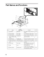
Part Names and Functions
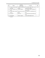
No.
Name
Indication
in this manual
Function
1 Clamp Table
Clamp table
The table on which the work is
placed
P.3-3
2 Power Off switch
Power switch
Turns off the power to the machine.
P.2-4
3 Power On switch
Power switch
Turns on the power to the machine.
P.2-4
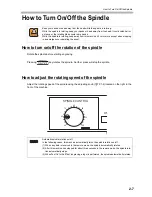
4 Knob to adjust the num-
ber of revolutions of the
spindle
Adjusting knob
Adjusts the number of revolutions
(rpm) of the spindle.
P.2-7
5 Operation Panel
Operation panel
The panel for operating the machine
P.2-2
6 Emergency Stop Switch
EMERGENCY switch
Stops the machine in an emergency.
P.2-5
7 Chip Removal Attach-
ment
Chip removal attachment
Vacuums dust and chips during
engraving.
P.1-8
8 Vacuum Hose
Vacuum hose
The hose which connects the chip
removal attachment to a cleaner
9 Head
Head
Performs engraving.
A cutter or a pen can be attached.
10
Reference Scale
Reference scale
Used as reference when setting the
work parallel to the machine.
P.3-3
Summary of Contents for ME-300STII
Page 12: ...12 Machine Specification 6 10 Interface Specification 6 11 Supported G code List 6 12...
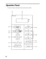
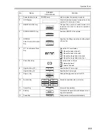
Page 26: ...2 2 Operation Panel The names and functions of the operation panel components are as follows...
Page 68: ...4 14...
Page 69: ...5 1 CHAPTER 5 ERRORS AND SOLUTIONS...
Page 76: ...5 8...
Page 77: ...6 1 CHAPTER 6 APPENDIX...
Page 89: ......

