3-8
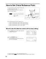
How to Set Z Axis Reference Point
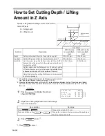
The Z axis reference point is a basis of cutting depth
and lifting amount of the cutter.
Be sure to set this when the power is turned on or
works or tools are replaced.
There are three ways to set Z axis reference point.
1) When “Auto flat detection switch” is OFF (manual setting)
*1
2) When “Auto flat detection switch” is OFF (automatic setting)
3) When “Auto flat detection switch” is ON or AUTO.
When the auto flat detection switch is OFF (manual setting)
1
Press
until the tip of the cutter meets the
surface of the work.
*2
2
Press
to set.
Please set again the origin that was set here when
you turn on the power again.
•
If a G-code is set using an operation
switch, set the origin using the G
Work Origin Menu.
(
P.4-12)
*1. For the auto flat switch, see "How to Set the Mode Switch" (P.4-7).
*2. When you press the
, you can change the transfer unit of Z-axis. (0.1mm
0.01mm)
Z axis reference
point
Cutting depth
Work
Lifting amount
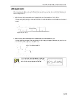
< M o v e >
S p i n . O F F
X a x i s
0 . 0 0 mm
Y a x i s
0 . 0 0 mm
Z a x i s
- 0 . 0 3 mm
< Z
S t a n d a r d >
Z a x i s
0 . 0 0 mm
Summary of Contents for ME-300STII
Page 12: ...12 Machine Specification 6 10 Interface Specification 6 11 Supported G code List 6 12...
Page 26: ...2 2 Operation Panel The names and functions of the operation panel components are as follows...
Page 68: ...4 14...
Page 69: ...5 1 CHAPTER 5 ERRORS AND SOLUTIONS...
Page 76: ...5 8...
Page 77: ...6 1 CHAPTER 6 APPENDIX...
Page 89: ......

