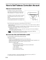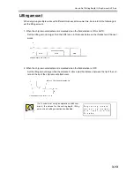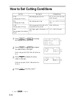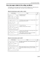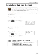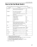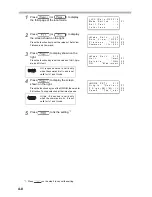
How to Set Flatness Correction Amount
3-11
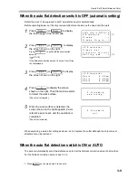
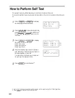
How to set
1
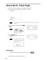
Set to the local mode, and stop the spindle if rotating.
2
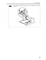
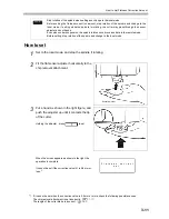
Fit the flat sensor adjuster horizontally to the
chip removal attachment.
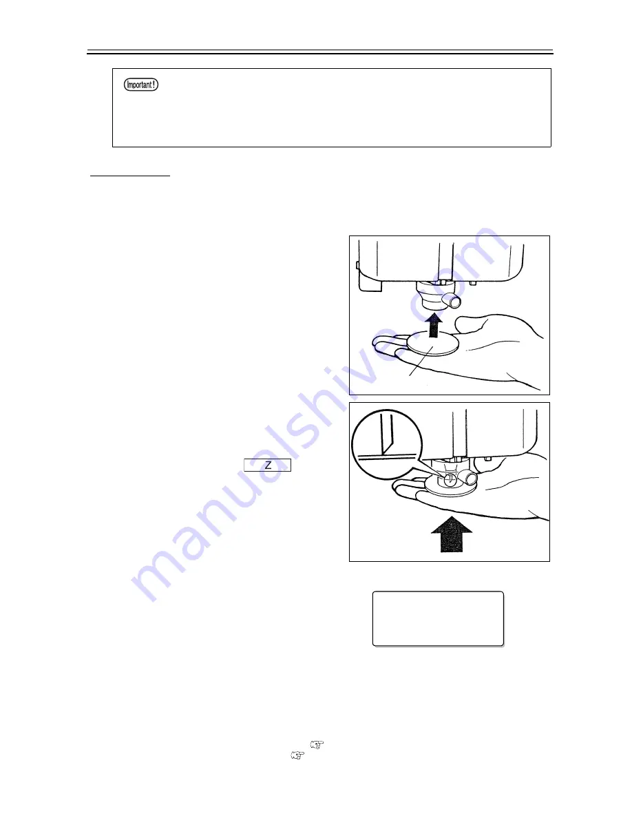
3
Put a hand as shown in the right figure, and
push the adjuster up until it contacts the tip
of the cutter.
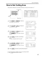
Holding the adjuster , press
to set.
When the screen appears as shown in the right, the
operation is complete.
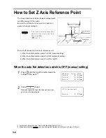
It cannot be set if the correction value (h) is 0.8 mm or
less.
*1
Stop rotation of the spindle when setting and change to the local mode.
Before setting the flatness correction amount, stop rotation of the spindle and change to the
local mode. If setting while the spindle is rotating, the cutter may pass through the sensor
adjuster and cut hands.
Even when under suspension, the spindle rotates once it receives data in the remote mode.
Before setting, stop rotation of the spindle and change to the local mode.
*1. If it cannot be set when the correction value is 0.8 mm or more, check the following possible causes.
The chip removal attachment is set incorrectly.
(
P.1-11)
The length of the cutter blade is incorrect.
(
P.6-2)
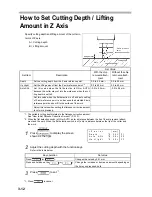
Sensor Adjuster
F l a t n e s s
c o r r e c t
s e t
Summary of Contents for ME-300STII
Page 12: ...12 Machine Specification 6 10 Interface Specification 6 11 Supported G code List 6 12...
Page 26: ...2 2 Operation Panel The names and functions of the operation panel components are as follows...
Page 68: ...4 14...
Page 69: ...5 1 CHAPTER 5 ERRORS AND SOLUTIONS...
Page 76: ...5 8...
Page 77: ...6 1 CHAPTER 6 APPENDIX...
Page 89: ......

