background image

1-2

Installing the device

Where to install the device

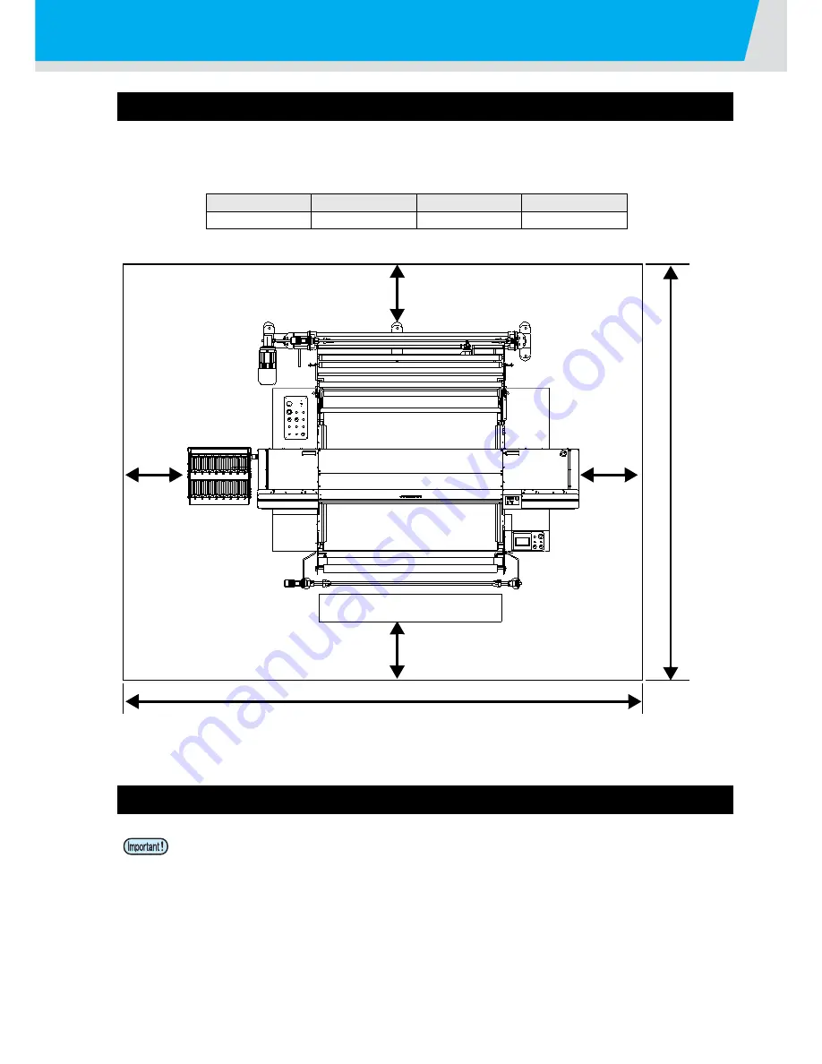
Secure sufficient space for installation before assembling this unit.
Decide the place considering the size of the device and a space required for execution of printing.

Moving This Machine

Machine Type

Depth

Height

Total Weight

4300 mm

3500 mm

1650 mm

2300 kg

• When the machine is moved to any place other than on the same step-free floor, contact your 

distributor or our service office.
If you move it by yourself, failure or damage may occur.
Be sure to request your distributor or our service office to move this machine.

6300 mm

1000 mm

or more

1000 mmor more

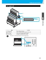
5500 mm

or more

1000 mm

or more

1000 mmor more

Summary of Contents for TEXTILE JET TX1800B

Page 1: ...MIMAKI ENGINEERING CO LTD URL http www mimaki co jp D202080 14 ...

Page 2: ...e of media feeding system 1 7 Ink supply unit 1 9 Names and function of the parts under the front cover 1 10 Carriage 1 10 Capping Station 1 11 Head height adjustment rod and adjustment screw 1 11 Other setting 1 12 For waste ink tank 1 12 Installing USB output driver 1 12 Setup of media feeding system 1 13 For opening closing cover 1 16 For opening closing cover 1 16 For power cable 1 17 Media 1 ...

Page 3: ...winding roller 2 18 Feed the media 2 20 Take up the media 2 26 Set the interleaving paper roll when using Rc210 ink 2 30 Adjusting the Head Height 2 32 Detecting the Media 2 34 When Changing the Origin 2 35 Test Printing 2 36 Test Printing 2 36 Performing Head Cleaning 2 37 Printing Data 2 38 Starting a Printing Operation 2 38 Suspending printing operation 2 39 Deleting Received Data Data Clear 2 ...

Page 4: ...e Capping Station 4 3 Cleaning the Ink cap 4 4 Cleaning the Wiper 4 5 When the message of Replace wiper is displayed 4 6 Cleaning the Head Nozzles 4 8 Maintenance of head nozzle surface 4 10 Wash ink discharge passage Drain Wash 4 17 When the Machine Is Not Used for a Long Time Storage Wash 4 19 Cleaning the Ink Head and the Area around It 4 21 If the Positions of Dots Shift 4 22 If nozzle cloggin...

Page 5: ... 6 Warning Error Messages 5 11 Warning Messages 5 11 Error Messages 5 13 About alarm display warning display of media feeding system 5 16 When power of adhesive weakened 5 18 Be sure to check before recoating adhesive 5 19 Peel weakened adhesive 5 21 Coat new adhesive 5 25 Chapter 6 Appendix Main Body Specifications 6 2 Ink Specifications 6 4 Inquiry Sheet 6 5 Function Flowchart 6 6 ...

Page 6: ...equipment is operated in a commercial environment This equipment generates uses and can radiate radio frequency energy and if not installed and used in accordance with the instruction manual may cause harmful interference to radio communications Operation of this equipment in a residential area is likely to cause harmful interference in which cause the user will be required to correct the interfer...

Page 7: ...hapter I and subchapter J indicates compliance with the CDRH regulations and is labeled on the product when marketed in the United States This Model is equivalent to Class II laser device according to CDRH Regulation This product complies with 21 CFR chapter I and subchapter J Use of controls adjustments or performance of procedures other than those specified in this manual may results in hazardou...

Page 8: ...also necessary to keep this Operation Manual on hand Make arrangements to deliver this Operation Manual to the person in charge of the operation of this device This Operation Manual has been carefully prepared for your easy understanding however please do not hesitate to contact a distributor in your district or our office if you have any inquiry Description contained in this Operation Manual are ...

Page 9: ...operation of the plotter The symbol indicates helpful information that will facilitate the use of the device Indicates the reference page for related contents The symbol indicates the case where some phenomenon that requires a CAUTION sign including DANGER and WARNING signs exists A concrete precaution precaution against an electric shock in the case of the sketch given on the left is shown in the...

Page 10: ...unit contains parts applied high voltage Carrying out electrical work by those unauthorized for that work is prohibited When you perform the maintenance works make sure to do it after turning off the main power circuit breaker If the maintenance is performed while the breaker is kept on there is a risk of causing electrical shock Some devices require one minute for discharging the electric charge ...

Page 11: ...ater the wound up fabric could be stained with color penetration to the back CAUTION Keep it away from direct sunlight Do not install on the uneven place Be sure to use in the environment below Operating environment 15 30 C 59 86 F 35 65 Rh 1 1 40 to 65 Rh to use a TPink Do not install on the vibrating place Do not install on the place where wind of the air conditioner etc directly blows against D...

Page 12: ... case where any of the warning label has become so soiled that the warning message is illegible or has come off purchase a new one from your local distributor or our office 1 Order No M901549 2 Order No M907092 3 Order No M906637 4 Order No M907647 5 Order No LSR 04 6 Order No M908801 7 Order No PA020 M 8 Order No LSR 06 9 Order No SF004 10E 10 Order No SF022 10E ...

Page 13: ...xii 1 2 3 4 5 6 How to Read This Operation Manual ...

Page 14: ...xiii ...

Page 15: ...9 Names and function of the parts under the front cover 1 10 Carriage 1 10 Capping Station 1 11 Head height adjustment rod and adjustment screw 1 11 Other setting 1 12 For waste ink tank 1 12 Installing USB output driver 1 12 Setup of media feeding system 1 13 For opening closing cover 1 16 For opening closing cover 1 16 For power cable 1 17 Media 1 18 Usable Sizes of Media 1 18 Precautions in han...

Page 16: ... This Machine Machine Type Depth Height Total Weight 4300 mm 3500 mm 1650 mm 2300 kg When the machine is moved to any place other than on the same step free floor contact your distributor or our service office If you move it by yourself failure or damage may occur Be sure to request your distributor or our service office to move this machine 6300 mm 1000 mm or more 1000 mmor more 5500 mm or more 1...

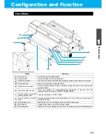
Page 17: ...chine and operation items 6 Operation panel Front There are buttons for manual automatic operations of take up unit the Emergency button and the RESET ALARM button 7 Power switch on media feeding system side All power switches of Tx400 1800B 8 Power switch on printer side The power switch of the printer If the switch of 7 is not ON you cannot turn on this power switch 9 Belt washing unit Washes in...

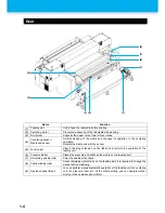
Page 18: ...ar Places the proper tension on the fabric and controls the operation of the feeding unit 6 Pressure Roller Places the pressure and attaches the media on the feeding belt 7 Smoothing wrinkle roller Smooths wrinkle of the fabric 8 Fabric winding roller Sucks remaining water drops on the feeding belt It is required to change the wound fabric periodically 9 Operation panel Rear You can perform manual...

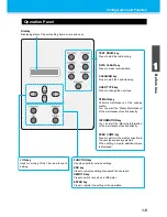
Page 19: ...setting items errors and so on TEST DRAW key Press to start the test printing DATA CLEAR key Press to erase received data INFORMATION key You can start the Machine Information of the maintenance function directly FEED COMP key Press to perform the media correction to the user type currently selected When setting a media additional menu is displayed CLEANING key Press to start the head cleaning USE...

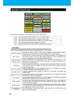
Page 20: ...y TAKE UP ON OFF TENSION BAR Switches valid invalid of the media end detection with the tension bar When this function is ON when the set time has passed with the tension bar at the lower position the status enters in the media end CENTERING ON OFF Switches valid invalid of the media centering unit When it is in ON status the centering unit adjusts the media position at feeding printing work WASHI...

Page 21: ...return the Emergency button button 2 to the original status and then press this button 2 Emergency button Immediately stop this machine under operation 3 TAKE UP MANUAL lever The rotating direction of the take up motor changes depending on the lever direction 4 TAKE UP AUTOMATIC lever Determines the media rotating direction of the take up device when you set BELT ON in the AUTOMATIC mode Rotate th...

Page 22: ...just even if you operate the lever After adjusting the position in the MANUAL mode change to the AUTOMATIC mode 6 AUTOMATIC lamp When it is in the AUTOMATIC mode this lights in green 7 FEEDING MANUAL lever The rotating direction of the take up motor changes depending on the lever direction 8 MEDIA END switch When it lights in green by pressing this the media end detection becomes valid 9 Air press...

Page 23: ... Set a dedicated ink pack 2 Ink pack slot Set an eco case with the ink pack of each color 3 Ink IC slot Set an ink IC provided with the ink pack 4 Ink slot lamp Indicates the condition of the ink pack The slot No on the display shows the slot of the figure below 1 2 3 4 Ink Pack 12345678ABCDEFGH ...

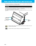
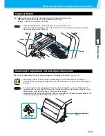
Page 24: ...for adjusting the head height according to the thickness of the fabric used The carriage moves during plotting and fabric detection When cleaning the capping station execute the STATION MAINTENANCE function to move the carriage P 4 3 Starting the plotting operation without adjusting the carriage height can cause damage not only to the fabric but also to the plotter itself When setting a fabric in ...

Page 25: ...g it with ink adhered may cause discharging defect due to clotted ink After setting a fabric be sure to adjust the head height If an operation such as printing etc is performed without adjusting the height the head may hit the fabric and it may cause the damage of the head It is recommended to use the equipment keeping the head height 3mm or more When using the equipment with the head height of 3m...

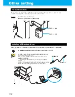
Page 26: ...will not leak Be careful not to turn over the waste ink tank For installation procedures follow the contents of the attached CD ROM Attach the attached ferrite core with the USB interface cable in advance refer to the right figure When connecting USB2 0 interface cable turn off the power supply of this machine It is necessary that the application you use supports USB2 0 interface If USB2 0 interfa...

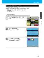
Page 27: ...ion touch panel perform the setting Setting of language to be displayed on the operation touch panel Normal setting Detailed setting Language setting 1 Press the SETUP on the operation touch panel 2 Press the LANGUAGE If you wish to cancel press the 3 Select language to be displayed Selectable language English Italian If you wish to cancel press the ...

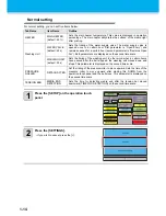
Page 28: ...ins opened for a certain hour second parameter is Remains Open For Both parameters are displayed on the second time scale WASHING UNIT default 30s Sets the timing of the washing unit In other word when a certain hours have passed after the belt stopped the washing unit moves down and stops This parameter is displayed on the second time scale PRESSURE ROLLER DETACH AFTER Set the timing of the press...

Page 29: ...Other setting 1 15 1 Before Use 3 4 5 6 3 Select the item to be set and set it by pressing the If you wish to cancel press the 4 Press the to return to the initial screen Press the of the item to be set ...

Page 30: ...to restart the computer 2 Close the cover and press the key Do not open the front cover and the maintenance cover L R while the plotter is in operation If you open the front cover or the maintenance cover L R during plotting the carriage will stop for safety reselting in abortion of plotting In this case re start the plotter and computer following the procedure described below Keep the front cover...

Page 31: ...ork Socket work to the breaker C type grounding work Special 3rd type grounding work Be careful so that the outlet is surely near this machine In addition set in the position where you can remove easily Doing the electrical work of this machine by other than a person who has the license of the electrical work is prohibited to prevent the electric shock Be careful not to perform faulty wiring It ma...

Page 32: ... on the center The belt encoder unit to feed the media correctly is attached on the right side of the media feeding system Be careful not to make the media hanging over the position of 25mm from the right edge of the media feeding system If you print with the media hanging over the belt encoder unit the media cannot be fed correctly and it may adversely affect the printing quality Be careful espec...

Page 33: ... or less Displacement of roll edge 15mm Cloth width of 500mm and less is 2mm Inner diameter of roll 2 3 inchs Fabric core strength Roll bend of 5mm or less when set with a fabric core thickness of 5mm or more Length of fabric core exposure from fabric 20mm or more Fixation with fabric core Tape at up to 3 points or weak adhesion Roll outer diameter 400mm or less Roll weight 44kg or less Print side...

Page 34: ...ay cause troubles In addition our company shall not hold responsible for faulty caused from refilling ink Do not touch or stain the contact of the cartridge PCB as this may cause failure of the PCB Request the treatment of used ink pack for industrial waste disposal contractor Do not shake the ink pack violently Shaking or turning it roughly can cause leakage of ink Open the ink pack just before a...

Page 35: ...as occurred in the relevant slot Alphabetic character side ink slot lamp Displays status of the alphabetic character side ink pack Alphabetic character side ink IC slot Set the ink IC for the alphabetic character side ink pack slot Alphabetic character side ink slot Set the eco case with ink pack Numeric character side ink pack slot Set the eco case with ink pack Numeric character side ink IC slot...

Page 36: ... Do not touch the metal part of the ink IC It may break the ink IC by static or may cause read error by stain or flaw 3 Put the 2L ink pack into the 2L eco case 1 Open the 2L eco case as shown on the right 2 Peel off the seal adhered on the connector part of the 2L ink pack 3 Put the 2L ink pack facing the connector down and close the 2L eco case 4 Attach an provided nameplate to the eco case 2L i...

Page 37: ...IC in the same one container box be sure to set in the same slot If they are set in different slots ink cannot be used in some cases Set the eco case vertically if it is set sidlingly the connector will be damaged and it may cause ink leakage Request the treatment of used ink pack for industrial waste disposal contractor When replacing ink pack with ink not empty follow the procedures below Otherw...

Page 38: ...he display language to Japanese here 1 Press the key in the local 2 Press to select DISPLAY 3 Press the key 4 Press to select JAPANESE Set Value ENGLISH JAPANESE PORTUGUESE ITALIANO ESPANOL FRANCAIS DEUTSCH TURKCE 5 Press the key 6 Press the key several times to end the setting FUNCT I ON SETUP ENT FUNCT I ON D I SP L AY ENT D I SP L AY ENGL I SH ENT D I SP L AY J APANESE ENT ...

Page 39: ...4 Starts detecting the roll media by pressing the key P 2 34 The display in LOCAL LOCA L 1 0 1 w i d t h 1 8 5 0mm Media width Displays current user type P 2 2 Machine name to identify the device P 3 27 The display in REMOTE REMOTE 1 0 1 5 MR R 0 0m Printed media width P 2 38 Machine name to identify the device P 3 27 Media correction value during printing P 2 39 The display during printing REMOTE...

Page 40: ...1 26 ...

Page 41: ...ater 2 12 Adjust the angle of the main heater 2 13 Setting a Media 2 14 Maximum Print Area 2 14 Notes for Setting a Media 2 14 Outline of media setting 2 15 About media route 2 15 Attach the fabric winding roller 2 18 Feed the media 2 20 Take up the media 2 26 Set the interleaving paper roll when using Rc210 ink 2 30 Adjusting the Head Height 2 32 Detecting the Media 2 34 When Changing the Origin ...

Page 42: ... 1 to 4 You can also select one by pressing the key 3 Press the key For Selecting a User Type without Using key You can select a user type by using the key in the printer mode without pressing the key Settings Reference Page Settings Reference Page Media Comp P 3 4 Refresh P 3 24 Media Feed P 3 6 mm inch Print Mode P 3 11 Auto Cleaning P 3 14 Ink Layers P 3 24 Color Pattern P 3 20 Drying Time P 3 ...

Page 43: ...ting a user type Test printing Printing Turning the power ON Setting media Refer to P 2 4 Turning the Power ON OFF Refer to P 2 2 Using the Registered User Types Refer to P 2 36 Test Printing Refer to P 2 38 Printing Data Refer to P 2 14 Setting a Media ...

Page 44: ...ront cover is open the operation does not start even if you turn the power supply ON When the power is turned on the firmware version is displayed following BOOT The message PLEASE WAIT appears on the LCD The screen turns to the media selecting 4 Turn ON the power supply of the media feeding system side Press the RESET ALARM button on the operation panel front When you press the RESET ALARM button...

Page 45: ...on touch panel alarm sections are displayed Press all alarm section buttons of 11 kinds to reset the alarm When it is reset they are displayed in green Press the to return to the initial screen Even if you press the alarm section button if it does not change to green it means an error occurs in that part Check the error contents ...

Page 46: ... the ALARMS display in red on the operation touch panel warning sections are displayed Press all warning section buttons of 4 kinds to reset the warning When it is reset they are displayed in green Press the to return to the initial screen ...

Page 47: ...roved If turning off by necessity work from Step 1 to 8 of P 4 8 Cleaning the Head Nozzles fill the cleaning liquid in the cap and then turn the power off In the control characteristics of this machine if the power is turned off for more than 12 hours ink may gradually be discharged from the head nozzle even if the head is capped If ink is discharged from the nozzle the color of ink may be mixed w...

Page 48: ... printing is controlled by the operation of the tension bar with two sensors Until the media is detected in the peeling sensor START located right behind the peeling roller the take up unit is in the idling status When it is detected the take up unit takes up the media until the peeling sensor STOP responds This process will repeat up to the end of the printing process Do not touch this machine du...

Page 49: ...or some of them depending on the kind of media Switch ON OFF of the centering unit By using the centering unit you can keep the media straight during printing However depending on the way of winding media the media may fold due to this centering operation 1 Switch by pressing the CENTERING ON OFF on the operation touch panel If you wish to change to ON lights in green If you wish to change to OFF ...

Page 50: ... pressing the WASHING ON OFF on the operation touch panel If you wish to change to ON lights in green If you wish to change to OFF lights in yellow The belt washing unit is ON only when the feeding belt is in the operation status Even if it is ON on the operation touch panel if the feeding belt is not in the operation status it will not operate ...

Page 51: ...dherence and dryness of the feeding belt 1 Switch by pressing the BELT HEATER on the operation touch panel If you wish to change to ON lights in green If you wish to change to OFF lights in yellow For the belt heater temperature setting refer to Normal setting P 1 14 When recoating adhesive be sure to turn this OFF Belt heater ...

Page 52: ...g the HEATER ON OFF on the operation touch panel If you wish to change to ON lights in green If you wish to change to OFF lights in yellow For the main heater temperature setting refer to Normal setting P 1 14 When recoating adhesive be sure to turn this OFF ...

Page 53: ...using the attached monkey wrench 2 Adjust the angle of the heater and tighten the hexagon head bolt When using the main heater make it parallel against the media surface from the free roller to the take up device The angle of the media surface differs depending on the take up method inward outward or the taken up amount of the media Adjust the angle of the main heater with two persons or more with...

Page 54: ... of the fabric can be reduced using a guiding fabric The roll shaft for setting the roll media is heavy weighing 8 to 10 kg only with the shaft itself When setting take care not to drop the media or the roll shaft on your foot etc It could cause injury due to its heavy weight This operation should be performed by 2 or more person bcause the roll is heavy in weight 10mm 10mm n the case of roll medi...

Page 55: ...ng of the media smoothly As the pressure roller is a heavy roll much care should be taken for falling of the roller and being wedged during media setting Attach the fabric winding roller P 2 18 To prevent the media from being stained prepare the fabric winding roller Take up the media P 2 26 Fix the media on the paper core and take up it Feed the media P 2 20 Set the media and feed it to the take ...

Page 56: ...ying appropriate tension for the media there is a need for adjusting the weight of the tension bar Reference for weight adjustment Check whether the tension suited for the media is applied on by referring to the phenomenon below If the proper tension is not applied on the media it is required to adjust the number of counter weights Weight Media surface Status at feeding Not enough Partial waviness...

Page 57: ...h for 2000g 1300g 600g 300g and 100g 3 Attach the weight fixing screw Be sure to attach the weight fixing screw so that the attached counter weight may not fall Be sure to attach the counter weights of the same weight both for right and left If the weights are different feeding defect may occur After attaching the counter weight perform test print to check that the tension is suitable for the medi...

Page 58: ...inding roller The fabric winding roller is located in the rear surface of this machine and around the feeding belt roller 2 Wind the fabric on the fabric winding roller 1 Align the roller with the fabric as indicated in the right figure 2 Fix the roller and the fabric with adhesive tape 3 Wind the fabric on the roller and fix it with adhesive tape Before shipment the fabric winding roller had no f...

Page 59: ...c winding roller with the fabric Attach the fabric winding roller by aligning it with the groove of the resin block around the feeding belt roller on the rear surface of this machine 4 Rotate the feeding belt to check that the fabric winding roller can rotate smoothly ...

Page 60: ... up inwards or outwards For details refer to the table below 3 Rotate and adjust the CENTERING MANUAL lever on the rear surface control panel so that the centering unit may be located at the center of the centering area Print side FEEDING AUTOMATIC lever FEEDING MANUAL lever Taking up outwards Rotate counterclockwise When feeding media When taking up media Rotate clockwise Rotate counterclockwise ...

Page 61: ...x the roll holder and the paper core with tape 5 Set the roll shaft on the feeding unit 6 Return the shaft fixing collar to the original position 5 Rotate the FEEDING MANUAL lever on the rear surface control panel to feed the media Feed it by about 3m Before moving the shaft fixing collar be sure to check that the roll shaft slot turns up If you move the shaft fixing collar with the roll shaft slo...

Page 62: ...ough the turning bar located on the upper side of the pressure roller wind the media on the pressure roller To prevent injury from unexpected falling of the pressure roller be sure to push the safety pins Check that the safety pin comes out completely If it does not come out completely it cannot prevent the pressure roller from falling Smoothing wrinkle roll bar can function when the media is set ...

Page 63: ...ssure depending on the media to be used Depending on the kind of the media to be used pre treatment and adhesive status pressure adjustment is required in some cases For reference for stretch material make the pressure lighter and for non stretch material make the pressure stronger After printing starts also check the peeling status of the fabric on the take up side of this machine to fine adjust ...

Page 64: ...ronger 14 Pressing the FEEDING OFF CENTERING OFF on the operation touch panel switch the status to the FEEDING ON CENTERING ON For the media with much weaving stretch material etc the effect of centering cannot be expected in some cases even if you use the centering unit Be sure to perform test printing to check if the centering functions effectively before using it If media windles or wrinkle occ...

Page 65: ...h as break of printer or media deterioration of printing quality etc caused from performing back feed our company shall not hold responsible So please be careful about it If the media cannot be fed normally the warning error DANCING BAR ANOMALY occurs In such a case release the warning by following the procedures below 1 Rotate the FEEDING MANUAL lever of the rear surface control panel to move the...

Page 66: ...ke the status to MANUAL 2 Press PRESSURE ROLLER UP to change it to DOWN 3 Set the speed to about 10m min by pressing the BELT SPEED 4 Press the BELT OFF to make it to BELT ON Belt will operate and feed the media If enough amount of media is taken up to fix the media to fabric core press the BELT ON and switch to the BELT OFF ...

Page 67: ...ol panel to wind the media The rotation direction of the TAKE UP MANUAL lever is determined by the direction of the TAKE UP AUTOMATIC lever The direction of the FEEDING AUTOMATIC lever is determined by the print side either taking up inwards or outwards For details refer to the table below Wind the media making going round at least twice to prevent the media from falling from the paper core When y...

Page 68: ...ensor The peeling sensor can detect the media when the media shades light emitting from the sensor When using firm media or wider media the media cannot be detected in some cases because light emitting from the sensor is not shaded much When using such media to make the media can shade the sensor light by slanting the media edge with the fabric guide in order to detect the media easily Make the am...

Page 69: ... printing status 13 Output the printed data When the setting of the media feeding system and the Tx400 are completed output the printed data and start printing When using the external heater the heat of the heater may be directly applied to the cover of the machine the heater unit cable etc and they may reach a high temperature Though we inform you of that by pasting the caution label on the posit...

Page 70: ... shaft through the interleaving paper roll 3 attach the connection shaft with the interleaving paper roll set on the shaft holder attach the interleaving paper roll at the center 4 Perform the work in P 2 20 Feed the media and feed the media to the take up side of the machine front surface 5 Perform the work up to the Step 6 in P 2 26 Take up the media and fix the media on the paper core Please us...

Page 71: ...eaving paper and fix the top edge of it on the paper core on which the media was pasted with tape Fix the interleaving paper with adhesive tape 7 Perform the work from the Step 7 in P 2 26 Take up the media and wind the media and the interleaving paper on the paper core ...

Page 72: ...ed Perform the head height adjustment each time when you change the fabric When the height of the head is set at 1 3mm minimum value from the surface of the platen pay attention to the following points 1 Use the fabric with surface without wrinkles and convex concave shapes The fabric and the head may graze with each other or the fabric may be caught and pressed by the head causing a jam of being ...

Page 73: ...ht adjusting rod touches the surface of the fabric the distance between the head and printing surface of the fabric will become optimum Even if you raise the head height if the adjustment is made so that the tip of the height adjusting rod touches the surface of the fabric the distance between the printing surface and the head is not changed If you wish to avoid the fluff on the surface of the fab...

Page 74: ...ss the key to select MANUAL 2 Press the key The carriage moves 5 Set the printing origin 1 Press to move the carriage to the print start position origin Put an arrow mark of the carriage on the setting position 2 Press the key If MANUAL is set on the Step 5 go to the Step 7 If a number is entered for the printing width on the Step 5 the left end of the printing area is automatically adjusted to th...

Page 75: ...anging the Origin 1 Press in LOCAL to adjust the Origin to the position Select the carriage and media moving the point with the 2 After determining the origin press the key The origin is changed If you set the wrong printing area detect again from the Step 1 after performing the operation below 1 Press the key 2 Press to select MEDIA SET 3 Press the key 4 Press to select RESET 5 Press the key O r ...

Page 76: ...t is normal end the operation When the result is abnormal perform head cleaning P 2 37 When using a leaf media set the media larger than the A3 size placed sideways When using a roll media check the media is not slacken Check before test printing If a media has been set P 2 14 If the origin position has been set If the head gap has been adjusted P 2 32 TEST PR I NT ENT TEST PR I NT P r i n t i n g...

Page 77: ...ws 4 Press the key 5 Press to select a type of cleaning 6 Press the key twice The remaining cleaning time is indicated in the lower part of the display When cleaning has ended the screen returns to LOCAL 7 Perform test printing again to check the result Repeat the cleaning and test printing until the result becomes normal When image quality is not improved even though head cleaning is repeated Cle...

Page 78: ...mation of the printing being executed is displayed P 1 25 6 After the printing operation is completed press the key to put the mode back into the LOCAL If the transmission of the data from the computer is cut over 30 seconds the message as shown in the right is displayed LOCA L w i d t h mm REMOTE 5 0 0m REMOTE 3 0 0 x 3 0 0 A L L 4 PU W3 2 1 0 0m REMOTE 5 MR 0 0m Division number P Pass H Double s...

Page 79: ...be made beautifully with the feed quantity set by the obtained value through the media correction due to the difference in yarn count or weaving method When stripes appear in the printed image while printing make the corrections performing the following steps 1 Press the key during printing Displays the current correction value 2 Press the key Displays the correction value input screen 3 Press to ...

Page 80: ...2 40 ...

Page 81: ...Setting Automatic Cleaning 3 14 Setting of cleaning before printing 3 14 Setting of cleaning while printing 3 15 Setting of cleaning after printing 3 17 Setting of Power ON cleaning 3 19 Setting Color pattern 3 20 Setting Drying Time 3 21 When moire fringes occur during printing 3 22 Other Settings 3 24 Machine settings 3 25 Switch head to use 3 26 Set machine name 3 27 Set stamp 3 28 Performing s...

Page 82: ... optimum printing condition only by changing one user type to another Example of Type Registration How to Register User Types 1 Press the key in LOCAL 2 Press the key 3 Press to select one of the types 1 to 4 and press the key 4 Select and set each item of List of Functions to Be Set For details on how to set each function see the reference page contained in P 3 3 List of Functions to Be Set in Us...

Page 83: ...ers P 3 24 1 to 9 Used to set the number of multi layer print ing Priority P 3 13 HOST PLOT Used to set the priority order of settings by host plot Media Comp Print Mode Ink Layers Refresh Use Head Drying Time Feed Speed Refresh P 3 24 LEVEL 0 refreshing interval is long 1 3 refreshing interval is short Used to set the refreshing interval of the ink head during printing mm inch P 3 24 mm inch Used...

Page 84: ...URE ROLLER UP to change it to DOWN Refer to the assistant function P 2 9 to change the required function to ON 3 Press the key in LOCAL 4 Press to set the origin position 5 Press the key 6 Press to enter the width of the cloth set in the Step 1 7 Press the key to print a correction pattern 8 Press to move the correction pattern to the position where it can be easily seen 9 Press the key The screen...

Page 85: ...the correction is required operate procedures from the Step 3 to 9 to correct 12 Press the key several times to end the setting Performing the media correction without key Media correction is selectable from the local by using the key not by pressing the key To make effective the value set while printing set the priority order of the media correction on the Panel referring to P 3 13 Setting Priori...

Page 86: ...nting making the feeding speed before shipment 100 Select 90 if you wish to feed at 90 speed of that before shipment Feed speed 10 to 100 7 Press the key 8 Press the key several times to end the setting To make effective the value set while printing set the priority order of the media feed on the Panel referring to P 3 13 Setting Priority Order FUNCT I ON SETUP ENT SETUP S e l e c t TYPE 1 TYPE 1 ...

Page 87: ...ng the jog speed before shipment 100 Select 90 if you wish to move at 90 speed of that before shipment Jog Speed 10 to 100 9 Press the key 10 Press the key several times to end the setting When adhesive of the belt becomes weak the media may not adhere to strongly In this case make the feeding speed the jog speed slower you may be able to keep the adhesion FUNCT I ON SETUP ENT SETUP S e l e c t TY...

Page 88: ...ting value selected here the setting method differs When you selected ON perform the procedures from the Step 11 When you selected OFF proceed to the Step 10 and perform the setting of Belt Joint Adj When you make the belt encoder setting to ON printing quality is improved however the printing speed becomes slower than it is OFF When feeding unevenness may occur at the joint of the belt set the be...

Page 89: ...Level 0 to 3 Joint Adj becomes valid The amount of correction is smaller for Level 0 and is the biggest for Level 3 It is recommended to set Level 1 to the front side and Level 0 to the rear side OFF Joint Adj is not performed 11 Press the key 12 Press the key several times to end the setting B e l t J o i n t A d j F OF F R OF F B e l t J o i n t A d j F L e v e l 1 R L e v e l 0 TYPE 1 B e l t E...

Page 90: ...nt is smaller for Level 0 and is the biggest for Level 3 It is recommended to set this to Level 0 OFF The softness correction is not performed 9 Press the key 10 Press the key several times to end the setting When you set the softness valid the print quality with lower pass 6 pass and below may be degraded in some cases Be sure to check the printed image and perform the correction setting valid in...

Page 91: ...he setting items The setting contents vary depending on the resolution set in the Step 6 and 8 Please refer to the Combination of Factors That Can Be Set in the next page Set Item Overview Scanning direction Number of passes Set the direction for scanning and the number of pass BI D Printing is performed in both outward and return directions of the carriage Select this when you want to print in a ...

Page 92: ...ce white lines or blur Resolution dpi Bidirectional Unidirectional Resolution dpi Bidirectional Unidirectional Pass High Speed Pass High Speed Pass High Speed Pass High Speed 300x300 dpi 2 2 600x600 dpi 4 4 4 4 8 8 ON OFF 8 8 16 16 300x450 1 dpi 1 Even with the use of 4 color ink set the number of pass does not change 3 3 600x900 dpi 6 6 6 6 12 12 ON OFF 12 12 24 24 300x600 dpi 4 4 900x450 1 dpi 3...

Page 93: ...Press to select HOST or PLOT 7 Press the key 8 Perform the same operations as in Steps 6 and 7 to set other items 9 Press the key several times to end the setting Set Value Overview HOST Settings made in the computer Host are treated preferentially PLOT Settings made in this equipment Plot are treated preferentially Even with the setting by the host being prioritized the items set by the panel bec...

Page 94: ...Press to select Auto Cleaning 5 Press the key 6 Press the key 7 Press to select ON or OFF 8 Press the key 9 Press the key several times to end the setting Set Item Overview ON Cleaning is performed before starting the printing OFF Cleaning is not made before printing The cleaning before printing is performed when printing is made in Remote The cleaning is not performed before the test printing or ...

Page 95: ...l between each cleaning operation print length Priority Boundary Length Set the cleaning method when you print repeatedly using copy function of RIP you use To prevent the head from being damaged be sure to use it making the cleaning during printing to ON when you print for a long time When you wish to perform cleaning during printing start printing after wipe off ink adhering to the head and arou...

Page 96: ...select the cleaning method when you printed using copy function of RIP Select a setting value from either of below Boundary Perform cleaning between printing data Length Perform cleaning at the cleaning intervals printing length set in the Step 15 18 Press the key 19 Press the key several times to end the setting The setting performed here is only valid when you printed with the copy function of R...

Page 97: ...ng OFF proceed to Step 13 9 Press the key Set Item Set Value Overview Type Normal Soft Hard Mix A cleaning type is selected time 1 to 60min Set time up to performing cleaning automatically after printing If the function is set and performed on the operation panel cleaning is not performed When it returns to the local mode and one minute has passed cleaning starts When you select cleaning and perfo...

Page 98: ...rd 11 Press the key 12 Pressing select time up to starting cleaning after printing Set Value 1 to 60min 13 Press the key 14 Press the key several times to end the setting TYPE 1 T y p e S o f t TYPE 1 t i me 1m i n TYPE 1 t i me 1 0m i n TYPE 1 A f t e r P r i n t i n g ENT ...

Page 99: ... 1 to 4 and press the key 4 Press to select Auto Cleaning 5 Press the key 6 Press to select Power ON 7 Press the key 8 Press to select ON or OFF 9 Press the key 10 Press the key several times to end the setting Set Value Overview ON Performs head cleaning at turning ON the power supply OFF Does not perform head cleaning at turning ON the power supply FUNCT I ON SETUP ENT SETUP S e l e c t TYPE 1 T...

Page 100: ...the key 8 Press to set drying time Set Value 5 to 50mm 9 Press the key 10 Press the key several times to end the setting Set Value Overview ON Space 5 to 50mm The color pattern to check the nozzle missing may be printed beside the images Also the space between the image and the color pattern OFF FUNCT I ON SETUP ENT SETUP S e l e c t TYPE 1 TYPE 1 Co l o r P a t t e r n ENT TYPE 1 Co l o r P a t t...

Page 101: ...t drying time Set Value 0 0 to 10 0 sec 7 Press the key 8 Press the key several times to end the setting Set Item Set Value Overview Each Line 0 0 to 10 0sec Ink drying time for each scanning is set During bidirectional printing the machine stops for a certain period of time specified for each of the outward and return scanning FUNCT I ON SETUP ENT SETUP S e l e c t TYPE 1 TYPE 1 D r y i n g T i m...

Page 102: ...rform the procedures below 1 Terminate printing by pressing the key again 2 Operate the procedures from the Step 2 and set the value to other than MR1 in the Step 7 3 Press the key several times to return the mode to local 4 Press the key to restart printing and check the moire fringes Until you can check that the moire fringes have been reduced change the setting value of MR1 to MR5 and check Set...

Page 103: ...such a case select the setting value whose moire fringes have been most reduced among MR1 to MR5 In addition by changing the resolution the moire fringes may be reduced Depending on the image to be printed the setting value to reduce the moire fringes differs Even if you set the value suitable for reducing the moire fringes here the moire may occur in other image ...

Page 104: ...s the key 4 Press to select an item to set See List of Functions to Be Set in User Types P 3 3 5 Press the key 6 Press to select a set values See List of Functions to Be Set in User Types P 3 3 7 Press the key Press the key several times to end the setting The set value is retained even when the power is turned OFF FUNCT I ON SETUP ENT SETUP S e l e c t TYPE 1 ...

Page 105: ...et for recognizing them when they are connected to one another with a USB 2 0 interface used Stamp Setup ON OFF Setting to output the output date and drawing conditions after the completion of printing List You can print the setting contents and the information of this machine Information See P 3 37 Confirming Machine Information Warning See P 3 29 Performing setting related to warning Blank Data ...

Page 106: ...Set Value A B C AB BC ALL 5 Press the key 6 Press the key several times to end the setting Set Value Overview A B C AB BC ALL A Use the head of the A line B Use the head of the B line C Use the head of the C line AB Use the heads of the A line and the B line BC Use the heads of the B line and the C line ALL Use all heads FUNCT I ON SETUP ENT FUNCT I ON MACH I NE SETUP ENT U s e He a d He a d L i n...

Page 107: ...select MACHINE SETUP 3 Press the key 4 Press to select Machine Name 5 Press the key 6 Press to select a machine name 01 to 99 7 Press the key 8 Press the key several times to end the setting FUNCT I ON SETUP ENT FUNCT I ON MACH I NE SETUP ENT MACH I NE SETUP U s e He a d ENT MACH I NE SETUP Ma c h i n e Name ENT ワイハ ー レヘ ル レヘ ル 9 1 0 Ma c h i n e Name T x 4 0 0 0 1 Ma c h i n e Name T x 4 0 0 1 0 ...

Page 108: ... Press to select one of the set values Set Value ON OFF 7 Press the key 8 Press the key several times to end the setting Set Value Overview ON Prints the print condition with an image data OFF Prints only an image data FUNCT I ON SETUP ENT FUNCT I ON MACH I NE SETUP ENT MACH I NE SETUP U s e He a d ENT MACH I NE SETUP S t amp S e t u p ENT ワイハ ー レヘ ル レヘ ル 9 1 0 S t amp S e t u p S t amp OF F S t a...

Page 109: ...ON OFF Perform setting of the replacing time for the mist fan filter or clearing of the used counter Nozzle Recovery ON OFF When Nozzle recovery registration of the maintenance function P 4 38 is valid and when you display the confirmation screen P 5 11 Warning Messages before starting printing set this to ON When this is set to OFF print is performed without displaying the confirmation screen at ...

Page 110: ...t the printing distance until the warning is displayed Set Value 0m to 30000m 9 Press the key 10 Press the key several times to end the setting If you set the value to 0m the warning is not displayed FUNCT I ON SETUP ENT FUNCT I ON MACH I NE SETUP ENT MACH I NE SETUP U s e He a d ENT MACH I NE SETUP Wa r n i n g ENT ワイハ ー レヘ ル レヘ ル 9 1 0 Wa r n i n g C l e a n Wi p e r ENT Wa r n i n g M i s t F a...

Page 111: ... Reset 9 Press the key twice The used counter is reset 10 Press the key several times to end the setting If you clear the counter the warning below becomes not displayed M i s t F a n C l e a n F i l t e r B e l t A d h e s i v e Re a p p l y A d h e s i v e FUNCT I ON SETUP ENT FUNCT I ON MACH I NE SETUP ENT MACH I NE SETUP U s e He a d ENT MACH I NE SETUP Wa r n i n g ENT ワイハ ー レヘ ル レヘ ル 9 1 0 W...

Page 112: ...alues Set Value ON OFF 9 Press the key 10 Press the key several times to end the setting FUNCT I ON SETUP ENT FUNCT I ON MACH I NE SETUP ENT MACH I NE SETUP U s e He a d ENT MACH I NE SETUP Wa r n i n g ENT ワイハ ー レヘ ル レヘ ル 9 1 0 Wa r n i n g C l e a n Wi p e r ENT Wa r n i n g No z z l e Re c o v e r y ENT ワイハ ー レヘ ル レヘ ル 9 1 0 No z z l e Re c o v e r y A c t L i m i t ON No z z l e Re c o v e r y...

Page 113: ...f the set values Set Value Valid Invalid 7 Press the key 8 Press the key several times to end the setting Set Value Overview Valid Perform printing by feeding the blank part Invalid Perform printing by deleting the blank part Blank data Print data FUNCT I ON SETUP ENT FUNCT I ON MACH I NE SETUP ENT MACH I NE SETUP U s e He a d ENT MACH I NE SETUP B l a n k Da t a ENT ワイハ ー レヘ ル レヘ ル 9 1 0 B l a n ...

Page 114: ...ult as printing feeding speed becomes slower compared with that when feeding media with the jog key After dryness feed ends there are blank data by the length set in Step 12 feed length Media can be rewinded by pressing the jog key but media remains sticking on the belt and it may get into the lower side of the belt Also in the case you rewind the media the media at the feeding unit side bends Che...

Page 115: ...itions make this AUTO 11 Press the key 12 Set the feed length by pressing or Set Value 10 to 2000mm 13 Press the key 14 Press the key several times to end the setting ワイハ ー レヘ ル レヘ ル 9 1 0 D r y n e s s F e e d S p e e d AUTO D r y n e s s F e e d S p e e d 3 0 mm s D r y n e s s F e e d F e e d L e n g t h 1 0 0 0mm D r y n e s s F e e d F e e d L e n g t h 1 5 0 0mm He a t e r S e t u p D r y n ...

Page 116: ...rence for the maintenance 1 Press the key in LOCAL 2 Press to select MACHINE SETUP 3 Press the key 4 Press to select List 5 Press the key 6 Press the key Printing the list will start FUNCT I ON SETUP ENT FUNCT I ON MACH I NE SETUP ENT MACH I NE SETUP U s e He a d ENT MACH I NE SETUP L i s t ENT L i s t P r i n t e n t L i s t P r i n t i n g ...

Page 117: ...rming the machine information without the key The information of this machine can be confirmed with the key in LOCAL without the key Item Overview Version This displays the version information of the machine Serial No This displays serial number Dealer No This displays dealer number In LOCAL press the key Press to select the MACHINE SETUP and press the Press to select the Information and press the...

Page 118: ...cted Counter log By pressing you can check the used counter of the mist fan and the adhesive on the belt Nozzle Recovery When pressing the resolution currently printed and the pass information whose recovery is possible of the used head are displayed I n k L e v e l 9 9 9 9 9 9 9 9 9 9 9 9 9 9 9 9 E r r o r I n f o D i s p l a y V k e y I n k L e v e 9 9 9 9 9 9 9 9 9 9 9 9 9 9 9 9 The displayed r...

Page 119: ...Not Used for a Long Time Storage Wash 4 19 Cleaning the Ink Head and the Area around It 4 21 If the Positions of Dots Shift 4 22 If nozzle clogging is not solved ink filling 4 24 About ink port discharging jig 4 24 Setting Regular Operations 4 36 Set flushing operation 4 36 Set cleaning operation 4 37 When nozzles missing can not be improved 4 38 Register setting deletion of the nozzle recovery fu...

Page 120: ...ture inside the machine can cause electric shock hazards or damage to the machine Do not use benzene thinner or any chemical agent containing an abrasive Such materials can deteriorate or deform the surface of the cover Do not apply a lubricant etc to any parts inside the machine Doing so can cause damage to the printerr mechanism Be careful so that the cleaning solution for maintenance or ink doe...

Page 121: ... use a cleaning kit and clean stick If you use the machine with the ink cap or the wiper dirty nozzle clogging may easily occur Clean the ink cap and the wiper when the work is completed daily or when the roll media is replaced Tools required for maintenance Cleaning solution bottle kit A29 PN SPC 0137 sold separately Dropper Clean stick SPC 0527 Gloves Do not move the carriage out of the capping ...

Page 122: ...enance 4 Close the maintenance cover R and press the key After its initial operation the machine returns to the media selection P 2 34 Performing the station maintenance without key ST MAINTENANCE is selectable from the local by using the key not by pressing the key If you use the machine with the ink cap dirty nozzle clogging may easily occur Clean the ink cap and the wiper when the work is compl...

Page 123: ...ff the ink sticking to the wiper cleaner with a clean stick dipped in cleaning solution for maintenance 5 Close the maintenance cover R and press the key After its initial operation the machine returns to the media selection P 2 34 If you use the machine with the wiper dirty nozzle clogging may easily occur Clean the ink cap and the wiper when the work is completed daily or when the roll media is ...

Page 124: ...he nozzle clogging There is no difference between front and back side of the wiper You can insert it facing either side to the front 6 Clean the wiper cleaner Wipe off the ink sticking to the wiper cleaner with a clean stick dipped in cleaning solution for maintenance A cleaning wiper SPA 0171 is an option Buy one through the dealer in your region or at our service office Do not select WIPER Excha...

Page 125: ...ove the sponge in the wiper frame and wash it with water 2 Dry the sponge and put it into the wiper frame again 9 Close the maintenance cover R and press the key After its initial operation the machine returns to the media selection P 2 34 Rotate to unused edge 1 Remove the wiper cover and take the wiper rubber out 2 Rotate the wiper rubber upward and downward Rotate it with the unused part upward...

Page 126: ...onge in the wiper frame and wash it with water 2 Dry the sponge and put it into the wiper frame again 7 Press the key Check the items on the right beforehand Is NEAR END or INK END displayed At the cleaning operation perform ink absorbing At this time if NEAR END or INK END is displayed cleaning operation cannot be performed Replace with the ink pack with enough ink Be careful so that you may not ...

Page 127: ...on the right is displayed for the time set in Step 10 After the time to be left as it is has passed absorb the cleaning solution filled up in the cap and perform cleaning When cleaning has ended the machine returns to the media selection P 2 34 When nozzle missing is not corrected even after this cleaning has been performed several times per form If nozzle clogging is not solved ink filling P 4 24...

Page 128: ...event that ink gets in eyes immediately rinse it off with water and consult a medical doctor Sb210 Maintenance cleaning solution is the dedicated cleaning solution used for NOZZLE CLEAN P 4 8 or for NOZZLE CLEAN 22 P 4 12 of the device with Sb210 Do not use Sb210 Main tenance cleaning solution for the device without Sb210 It may cause discharging defect Tools required for maintenance Maintenance c...

Page 129: ...ere is no ink blot or dust etc adhering to the tool If ink blot or dust etc adheres to the nozzle cleaning tool it will reduce the maintenance effect or cause the damage of the machine Before you use this nozzle cleaning tool remove the white protective film Fixing bracket Use this to fix the maintenance cloth Maintenance cloth Moisturize this with maintenance clean ing liquid Base Put the mainten...

Page 130: ...device 4 Remove the maintenance cover L 5 Wipe off ink sticking to around the head with a clean stick 6 After cleaning is completed close the maintenance cover L 7 Press the key Never rub the nozzles S t a t i o n S e l Ca r r i a g e Ou t S t a t i o n S e l No z z l e C l e a n 2 Ca r r i a g e Ma i n t e Comp l e t e d e n t C l e a n Wi p e r Comp l e t e d e n t ...

Page 131: ...frame again 11 Press the key 12 Open the maintenance cover R to clean the cap rubber Wipe off the ink sticking to the cap rubber with a clean stick dipped in cleaning solution for maintenance 13 Remove hardened ink etc remaining in the cap with a pair of tweezers 14 Press the key Be careful so that you may not get injured with the edge of the wiper cleaner If the sponge is misaligned or floats ret...

Page 132: ...he maintenance cloth out from the bag seal the bag rapidly in order to avoid dust etc entering in the bag Be sure to save the maintenance cloth in the bag in order to prevent it from touching dust etc Set it so that the base and the fixing bracket are not misaligned back and forth If you perform maintenance with it being misaligned it may dam age the nozzle surface Set it so that no ruck occurs on...

Page 133: ...you from not taking the cleaning tool out 22 Open the maintenance cover R and remove the nozzle cleaning tool Check that the maintenance cloth is fully moisturized If you perform maintenance using a dry maintenance cloth it may damage the nozzle sur face After raising the nozzle cleaning tool from the cap and by putting it on the waste cloth at once remove it paying attention not to drop maintenan...

Page 134: ...intenance cleaning liquid and wipe off ink adhering to the base and the fixing bracket 3 Save the cleaned nozzle cleaning tool in the bag Be careful about the nozzle cleaning tool preventing it from dust etc Fine dust or dirt on the nozzle cleaning tool base adheres to the cap Be sure to clean the cap rubber If you use this machine without cleaning the cap rubber there is the danger that the nozzl...

Page 135: ...s onto the platen Repeat the idle absorbing operation Absorption for 10 seconds and interruption for 10 seconds until the washing operation is completed 5 Open the maintenance cover R 6 Fill up the cap with cleaning solution for maintenance using a dropper When idle absorbing operation is stopped fill up the cap with cleaning solution on the verge of overflow from the cap Fill up all caps with cle...

Page 136: ...4 18 8 Press the key After performing idle absorbing operation for 30 min the machine returns to the media selection P 2 34 P l e a s e Wa i t MED I A SE L ECT ROL L L EAF ...

Page 137: ...ink is absorbed when the nozzles are washed At this time if the state of INK END or NEAR END is detected the nozzle washing operation cannot start Replace the ink pack with another from which the state of NEAR END or INK END is not detected In the control characteristics of this machine if the power is turned off for more than 12 hours ink may gradually be discharged from the head nozzle even if t...

Page 138: ...f cleaning solution and cleaning start When the cleaning is completed the head moves on to the platen 13 Clean the wiper and the wiper cleaner again and then press the key 14 Fill up the cap with cleaning solution for mainte nance using a dropper When idle absorbing operation is stopped fill up the cap with cleaning solution on the verge of overflow from the cap Fill up all caps with cleaning solu...

Page 139: ...rriage and press the key 4 Press the key Carriage will move to the left end of this device 2 Remove the maintenance cover L 3 Wipe off ink sticking to around the head with a clean stick 4 After cleaning is completed close the maintenance cover L 5 Press the key After its initial operation the machine returns to the media selection P 2 34 Tools needed for cleaning Cleaning solution bottle kit A29 P...

Page 140: ...to change it to BELT ON FEEDING ON and TAKE UP ON Press PRESSURE ROLLER UP to change it to DOWN Refer to the assistant function P 2 9 to change the required function to ON 3 Select Print Adjust of the maintenance menu 1 Press the key 2 Press to select MAINTENANCE and press the key 3 Press to select Print Adjust and press the key 4 Press to select resolution to be corrected Resolution 300dpi 450dpi...

Page 141: ...rn 1 Correction value 40 0 to 40 0 Check the test patterns The position where an outward feeding line and a return feeding line become one straight line is the correction value When the correction value in not between 40 0 and 40 0 adjust the height of the printing heads and then perform the operations in Step 2 and later 12 Press the key 13 In the same way as in Step 10 correct the dot position i...

Page 142: ...fter Performing Head Cleaning P 2 37 or Cleaning the Head Nozzles P 4 8 Normal Select if nozzle clogging cannot be solved even after performing ink filling in Soft After ink filling is completed check the status referring to Check ink filling status filling check P 4 34 Hard Select if nozzle clogging cannot be solved even after performing ink filling in Normal After ink filling is completed check ...

Page 143: ...d to perform ink filling Selecting head Press Performing ink filling Press When ink filling is not performed is displayed on the screen 3 Press the key 4 Press the key Ink is supplied automatically When ink has been supplied completely the screen returns to the shown on the right 5 Press the key several times to end the setting I n k F i l l i n g Co l o r 1 2 5 6 7 8 I n k F i l l i n g T y p e S...

Page 144: ...he key 4 Press to select Normal 5 Press the key twice Ink is supplied automatically When ink has been discharged completely the screen on the right appears 6 Open the maintenance cover R and remove the head maintenance cover 1 Open the maintenance cover R 2 Remove the head maintenance cover I n k F i l l i n g Co l o r 1 2 5 6 7 8 I n k F i l l i n g T y p e S o f t I n k F i l l i n g T y p e No ...

Page 145: ...ou hear it click 8 Remove ink blot of the pipe adapter of the ink port discharging jig Wipe ink blot etc of the pipe adapter with waste cloth immersed in cleaning liquid for maintenance If ink replacement is performed in the state of the waste ink bottle being slanted it may cause damages to the machine Be sure to paste the waste ink bottle making it vertical against the ground If you do not hear ...

Page 146: ...he ink port discharging jig is washed While taking out and putting in the pipe adapter hold the joint of the ink port with your fingers Otherwise the ink port may break and ink may leak Check that no loose exists on the nut of the coupling valve If the nut is loosened air will get mixed in the ink port and it cannot discharge ink properly Once the pipe adapter is put in the cleaning solution conti...

Page 147: ...Referring to the Step 7 attach the ink port discharging jig 14 For all selected ink ports perform the procedures from the Step 8 to 13 15 Remove the ink port discharging jig 16 Attach the head maintenance cover and close the maintenance cover R 17 Press the key Ink is supplied automatically When ink has been supplied completely the screen returns to the shown on the right 18 Press the key several ...

Page 148: ...the key 4 Press to select Hard 5 Press the key twice Ink is supplied automatically When ink has been discharged completely the screen on the right appears 6 Open the maintenance cover R and remove the head maintenance cover 1 Open the maintenance cover R 2 Remove the head maintenance cover I n k F i l l i n g Co l o r 1 2 5 6 7 8 I n k F i l l i n g T y p e S o f t I n k F i l l i n g T y p e Ha r...

Page 149: ...ou hear it click 8 Remove ink blot of the pipe adapter of the ink port discharging jig Wipe ink blot etc of the pipe adapter with waste cloth immersed in cleaning liquid for maintenance If ink replacement is performed in the state of the waste ink bottle being slanted it may cause damages to the machine Be sure to paste the waste ink bottle making it vertical against the ground If you do not hear ...

Page 150: ...he ink port discharging jig is washed While taking out and putting in the pipe adapter hold the joint of the ink port with your fingers Otherwise the ink port may break and ink may leak Check that no loose exists on the nut of the coupling valve If the nut is loosened air will get mixed in the ink port and it cannot discharge ink properly Once the pipe adapter is put in the cleaning solution conti...

Page 151: ...ch the ink port discharging jig 14 For all selected ink ports perform the procedures from the Step 8 to 13 15 Remove the ink port discharging jig 16 Attach the head maintenance cover and close the maintenance cover R 17 Press the key Ink is supplied automatically When ink has been supplied completely the screen returns to the shown on the right 18 Work from the Step 6 to the Step 17 again 19 Press...

Page 152: ...to select the head to be used for printing pattern Selecting head Press Performing printing Press If pattern printing is not performed is displayed on the screen 4 Press the key 5 Press to set the origin position 6 Press the key 7 Press to enter the print width Make the print width wider as much as possible If the print width is narrow you cannot fully check 8 Press the key Perform pattern printin...

Page 153: ...If nozzle clogging is not solved ink filling 4 35 1 2 3 4 Maintenance 6 9 Press the key several times to end the setting color 8 color 1 ...

Page 154: ...hrs 00min Move the cursor Press Set the time Press 6 Press the key 7 Press the key several times to end the setting Set Item Set Value Overview Flushing ON 0hr 01min to 24hrs 00min When a certain hour has passed if you wish to perform the flushing operation automatically set to ON and set the interval to perform the flushing operation OFF Flushing operation is not performed automatically Cleaning ...

Page 155: ...ress to select ON When selecting OFF proceed to Step 8 6 Press the key 7 Press to select the interval of the cleaning operation 0hr 01min to 24hrs 00min Move the cursor Press Set the time Press 8 Press the key 9 Press the key several times to end the setting Ro u t i n e Co n t r o l F l u s h i n g ENT テイキ セイキ ョ フラッシンク O N Ro u t i n e Co n t r o l C l e a n i n g ENT Ro u t i n e Co n t r o l C ...

Page 156: ...very 2 Press the key twice 3 Press to select Print When you choose Print the screen moves to the origin setting screen automatically 4 Press to select origin position 5 Press the key Set Item Overview Regist You can set delete the nozzle to recover Print the test pattern and specify the nozzle recovery Recovery You can set valid invalid of the nozzle recovery function by the nozzle line Check You ...

Page 157: ...1 110 121 130 141 150 161 170 181 1 10 21 30 41 50 61 70 81 90 101 110 121 130 141 150 161 170 181 1 10 21 30 41 50 61 70 81 90 101 110 121 130 141 150 161 170 181 1 10 21 30 41 50 61 70 81 90 101 110 121 130 141 150 161 170 181 1 10 21 30 41 50 61 70 81 90 101 110 121 130 141 150 161 170 181 1 10 21 30 41 50 61 70 81 90 101 110 121 130 141 150 161 170 181 1 2 3 4 5 6 7 8 1 10 21 30 41 50 61 70 81...

Page 158: ... Press to select Clear 4 Press to select a nozzle line whose setting will be deleted Select a head Line A Line B and Line C Select a nozzle line 1 to 8 If ALL is selected the contents set for all nozzle lines are deleted 5 Press the key The next nozzle line selection screen is displayed Perform the procedures in the Step 6 to select a nozzle line whose setting will be deleted 6 Press the key sever...

Page 159: ... to select Nozzle Recovery 2 Press the key 3 Press to select Recovery 4 Press the key 5 Press to select the setting for each nozzle line 1 Press to select a nozzle line 2 Press to select either of ON head number is displayed OFF is displayed 6 Press the key 7 Press the key several times to end the setting No z z l e Re c o v e r y Re g i s t No z z l e Re c o v e r y Re c o v e r y No z z l e Re c...

Page 160: ...y 7 Press to select pass 8 Press the key several times to end the confirmation No z z l e Re c o v e r y Re g i s t No z z l e Re c o v e r y Ch e c k No z z l e Re c o v e r y c h k DP I 1 2 0 0 x 1 2 0 0 No z z l e Re c o v e r y c h k DP I 6 0 0 x 6 0 0 R c v r y v a l i d X 2 3 4 _ 6 7 X 1 6 PH i d s a b l 1 2 _ _ 6 _ _ _ R c v r y v a l i d X 2 3 4 _ 6 7 X 8 pH i d s a b l 1 2 _ _ 6 _ _ _ The...

Page 161: ...ozzle Recovery 2 Press the key 3 Press to select List 4 Press the key 5 Press to select the list to print When you choose the list the screen moves to the origin setting screen automatically 6 Press to select origin position 7 Press the key 8 Press the key Printing starts No z z l e Re c o v e r y Re g i s t No z z l e Re c o v e r y L i s t No z z l e Re c o v e r y L i s t S e t t i n g Ch e c k...

Page 162: ...rom getting dirty 2 Move the waste ink to another polyethylene resin tank 3 Set the waste ink tank you made empty in this machine When purchasing spare waste ink tank contact nearest sales outlet or our sales office Prepare polyethylene resin tank to which the waste ink in advance When discarding waste ink be sure to wear the attached gloves to do the work If you get the ink on your skin or in you...

Page 163: ...st fan filter out 3 Clean the mist fan filter Wash the mist fan filter taken out and dry it 4 Bring the mist fan filter unit back to the original status 5 Clear the used counter of the mist fan filter Referring to Set the time for replacing the mist fan filter the time for recoating the adhesive on the belt P 3 30 clear the used counter ...

Page 164: ...isplay Description 1 1 1 Displays on the firmware version 1 40 or later Displays when the pressure is likely to exceed the controlled range When the screen shown on the left is displayed the pressure is in the controlled range You can print or perform cleaning normally However if it is left for a while it may exceed the controlled range and the screen shown as 2 may be displayed 2 The pressure has...

Page 165: ... is released and the negative pressure control starts Pressure is informed with the buzzer and the ink throttle lamp as well as the screen display Pressure Ink throttle lamp Buzzer High 2 75 Sounds 2 76 2 85 2 86 2 95 2 96 3 05 3 06 3 15 3 16 3 25 3 26 3 35 Stops Proper value 3 36 3 45 Stops Low 3 46 3 55 Stops 3 56 3 65 Sounds 3 66 3 75 3 76 3 85 3 86 3 95 3 96 4 05 4 06 4 15 4 16 A d j u s t T h...

Page 166: ...n the fabric is not taken up on the belt 1 Wipe inside the three circles of the light reflector with a cotton swab immersed in the washing liquid 2 Wipe the circles wiped in the Step 1 with a dry cotton swab 3 Wipe the three lens of the peeling sensor with a cotton swab immersed in the washing liquid 4 Wipe the lens wiped in the Step 3 with a dry cotton swab The peeling sensor may be dirty because...

Page 167: ... 3 If an error occurs in 2L ink pack or ink IC 5 4 If printing is terminated due to media feeding system error 5 6 Warning Error Messages 5 11 Warning Messages 5 11 Error Messages 5 13 About alarm display warning display of media feeding system 5 16 When power of adhesive weakened 5 18 Be sure to check before recoating adhesive 5 19 Peel weakened adhesive 5 21 Coat new adhesive 5 25 Chapter 5 Trou...

Page 168: ... machine The mode is not REMOTE Press the key to switch to REMOTE Printing is misaligned The fabric is fed sidling The fabric gets wrinkled Ink adhered to the fabric A preprocessed fabric which suits ink to use is not used Use a pre processed fabric which suits the ink A fabric which is wrinkled or folded at both edges is used Do not use fabrics which are wrinkled or folded at both edges A fabric ...

Page 169: ...Execute the Media correction function P 3 4 4 Change the drawing mode of RIP P 3 11 Disagreement in print positions between outward trip and homeward trip 1 Execute the Dot position correction function P 4 22 The respective color ink injected by the respective color heads do not properly overlap 1 Execute the Dot position correction function P 4 22 2 The head height is too high Use it with making ...

Page 170: ...ice In addition check ink leak as below 1 Open the lid of the inspection window located on the left side surface of the ink supply unit 1 Loosen the finger screw 2 Rotate the lid of the inspection window 2 Check if ink leak out Check the tray inside the ink supply unit If ink leak out you can find ink pool on the tray If you cannot check it because inside the ink supply unit is dark use a flashlig...

Page 171: ...laced at ink replacing the used amount of ink of the 2L ink pack is abnormal Replace the ink IC Ink IC is not set Set the ink IC The specified expiration date of an ink has passed Check that the ink IC of the displayed number is the one that was attached to the 2L ink pack Then check the expiration date of the 2L ink pack of the displayed number Life of the connector part of the 2L ink pack has be...

Page 172: ...MATIC they are automatically switched to FEED ON TAKE UP ON 3 Press the key on the operation panel to display the local screen 4 Press the key to restart printing When a warning error occurs in the media feeding system WARNINGS on the operation touch panel lights in red and the warning below is displayed on the Tx400 screen Depending on the status WARNINGS on the operation touch panel may switch t...

Page 173: ...arning proceed to the Step 3 When WARNINGS lights in green Check the status of media around the peeling sensor Check that waviness on left of the media is not extremely different from that on right around the peeling sensor and the fabric guide is set correctly P 2 14 Setting a Media After checking the media is set correctly proceed to the Step 3 3 Press the key on the operation panel to display t...

Page 174: ...the operation touch panel of the media feeding system to change it to MEDIA END OFF The media end warning was released 3 Press the key on the operation panel to display the local screen 4 Select restart or termination of printing When you restart printing press the key When you terminate printing press the key to delete the printing data If you print with the media feeding system is MEDIA END OFF ...

Page 175: ...rom the paper core Press TENSION BAR to make it lights in yellow When the media is not fed because the roll holder is not fixed firmly Fix the roll holder again so that the paper core does not move P 2 20 TENSION BAR lights in green Do not change it and leave it as it is 3 Press the key on the operation panel to display the local screen When printing is terminated the light of TENSION BAR changes ...

Page 176: ...inting press the key to delete the printing data If you print with the media feeding system is MEDIA END OFF status media end cannot be detected Be sure to print while checking the remaining amount of the media etc If you print without media printing may be performed on the belt REMOTE 1 0 1 A L L 8 PU W3 2 1 0 0m DATA CL EAR ...

Page 177: ...ture of the installation environment so that it is within the range of 15 C 59 F to 30 C 86 F The environmental temperature is below the operable temperature 4 C 39 F Adjust the temperature of the installation environment so that it is 4 C 39 F and higher The battery is dead Contact our service office or the distributor in your region Ink for cleaning or ink initial filling is not enough Replace t...

Page 178: ... 5 6 Releasing method of warning when BELT ENCODER is displayed A warning occurred in the media feeding system during printing Release the warning by referring to P 5 7 Releasing method of warning when X Unit is displayed Media end was detected in the media feeding system during printing Release the warning by referring to P 5 8 Releasing method of warning when Media End is displayed Time to clean...

Page 179: ...temperature of the head has been detected nnn nozzle that has an error An error occurred in detecting the linear encoder The machine received some data other than command data Securely connect the interface cable in position Any parameter outside the range of acceptable numeric values was received Check the output setting of the host computer Data outside the area available for printing was receiv...

Page 180: ...his machine due to the USB2 0 connection Check that the cable is securely connected Also check to see if any error has occurred in the host computer The function setting has been changed or an unavailable function has been commanded while an unfinished printing job remains in the queue Finish printing all the data that has been received by the machine or clear the remaining data and then try again...

Page 181: ...FF the power to the machine and turn it ON again after a while If the same error message appears again contact our service office or the distributor in your region Ink supply from the 2L ink pack could not be performed Turn OFF the power to the machine and turn it ON again after a while If the same error message appears again contact our service office or the distributor in your region Ink could n...

Page 182: ...al problem in the take up unit FEEDING THERMIC SWITCH There is an electrical problem in the feeding unit CENTERING THERMIC SWITCH There is an electrical problem in the centering unit BRUSHER THERMIC SWITCH There is an electrical problem in the brush motor of the washing unit INVERTER WARNING There is an electrical problem in the main motor driving the belt MISSING AIR The air pressure is 6 bars or...

Page 183: ...stment The tilt of the media edge by the fabric edge guide is less Adhesion power of adhesive is off balance Even if you make surface waviness of right and left even at setting the fabric as adhesion power of adhesive is off balance the peeling position of the fabric height is much different between right and left Therefore the warning may occur Recoat adhesive or change the setting position of th...

Page 184: ... pressure of the pressure roller increases MAX 0 bar Also in case that adhesive power is too strong turn the adjustment dial and increase the air pressure Then pressure of the pressure roller decreases If you set time to recoat adhesive you can perform work without being worried about it P 3 30 Set the time for replacing the mist fan filter the time for recoating the adhesive on the belt When the ...

Page 185: ...e When you reapply adhesive please make sure to attach heater guard tray yellow In case that you accidentally dropped the adhesive or remover on the external side of the right and left of the belt please remove heater guard tray wipe off the dropped adhesive or remover and reattach the tray In case that you remove the heater guard tray please do not spill the adhesive or remover dropped inside the...

Page 186: ... media and adjust the pressure of the pressure roller When increasing the pressure of pressure roller Rotate the adjusting dial to the right to lower the value of the pressure indicator When media floats in the carriage operation area Increase the pressure of the pressure roller When media is apart from the belt before take up starts Increase the pressure of the pressure roller When media is not p...

Page 187: ...d dark place for storing hazardous objects When removing adhesive keep fire away and be sure to turn OFF the belt heater and the main heater In addition be sure to start the work after one hour and more have passed since the heater was turned OFF Be sure to provide adequate ventilation when removing adhesive Item to be used Item to be prepared Doctor Gloves Plastic coma attached to this machine Re...

Page 188: ...check that there is not the fabric or other object on the feeding belt and then press the BELT OFF to operate the belt When switching to the BELT ON the belt starts to move 7 Set the cloth on the side for applying kerosene diesel oil of the doctor to immerse kerosene diesel oil evenly Check that the belt heater and the main heater are OFF yellow ...

Page 189: ... remover may adhere to other parts such as washing unit etc it may adhere to adhesive again and cause the fixation fault Be careful not to accrete kerosene diesel oil on the belt encoder roller in the right side of this machine front and rear total 2 positions For the attached remover as standard the used amount is about 5 liters For Polix resin SX kerosene diesel oil shall be about one liter as t...

Page 190: ...eck whether there is any adhesive left not being peeled or large dust If adhesive is newly coated with any adhesive left on the belt surface concavity and convexity are generated on that part and it may influence on printing result After the belt surface is dehydrated coat new adhesive next page Perfuse gelled liquid including peeled remover onto a waste cloth etc and discard after dehydrating it ...

Page 191: ... is solvent pressure sensitive adhesive Be sure to wear the protection mask for organic solvent the goggle and the gloves to recoat adhesive When recoating adhesive be sure to use the chemical proof kerosene proof gloves When you recoat adhesive in the room with poor ventilation or hermetically closed room be sure to set up the ventilation equipment When using adhesive be sure to comply with Ordin...

Page 192: ...ve tape pasted on the belt paste one plastic coma each for right and left on the side with adhesive coated of the doctor Check the chemistry of adhesive tape with adhesive before using Check that tape does not melt by adhesive Paste adhesive tape as indicated in the right figure not to be peeled off by the doctor even after the belt goes round Belt upper surface Fabric feeding direction Main body ...

Page 193: ...ake the status to MANUAL 5 Pressing the BELT SPEED adjust it to 10 to 12m min 6 First check that there is not the fabric or other object on the feeding belt and then press the BELT OFF to operate the belt When switching to the BELT ON the belt starts to move Check that the belt heater and the main heater are OFF yellow ...

Page 194: ...e main heater OFF during leaving If you pour large amount of adhesive at a time it may overflow from right and left or it may drip off on the floor If overflow adhesive drops on the belt heater just below it there is danger of fire 1 Do not pour adhesive in a breath 1 Be sure to turn OFF the belt heater and the main heater If adhesive dropped on the belt heater or the main heater immediately turn ...

Page 195: ...When power of adhesive weakened 5 29 1 2 3 4 5 Troubleshooting 11 Switch to the BELT OFF to stop the belt ...

Page 196: ...5 30 ...

Page 197: ...This chapter contains the lists of the specifications and functions of this machine Main Body Specifications 6 2 Ink Specifications 6 4 Inquiry Sheet 6 5 Function Flowchart 6 6 Chapter 6 Appendix ...

Page 198: ...bidirection 300 x 600 dpi 2 4 8 pass Unidirection bidirection 450 x 450 dpi 3 6 12 pass Unidirection bidirection 450 x 600 dpi 2 4 8 pass Unidirection bidirection 600 x 300 dpi 1 2 4 pass Unidirection bidirection 600 x 450 dpi 3 6 12 pass Unidirection bidirection 600 x 600 dpi 2 4 8 pass Unidirection bidirection 600 x 900 dpi 3 6 12 pass Unidirection bidirection 900 x 450 dpi 3 6 12 pass Unidirect...

Page 199: ...ment Variable between 1 3mm and 7mm from the lower face of the media Waste ink tank Bottle type 10 liters Interface USB 2 0 Command MRL III MIMAKI original command Noise During standby Less than 58 dB FAST A back and forth and around Continuous operation noise Less than 65 dB Noise during discontinuous printing Less than 70 dB Safety standards to be met VCCI Class A FCC Class A UL 60950 1 CE Marki...

Page 200: ...enta Blue Orange Amount of supplied ink 2 liter Shelf life Written on the ink pack Within six months from unsealing or within valid duration written on the ink pack Storage temperature During storage 0 C to 40 C 32 F to 104 F For 40 C 104 F within one month During transpor tation 0 C to 40 C 32 F to 140 F For 60 C 140 F within 120 hours For 40 C 104 F within one month Do not disassemble the ink pa...

Page 201: ...achine Fill in the following necessary items and fax the sheet to our service office Company name Person in charge Phone number Machine model Used OS Machine information 1 1 See Confirming Machine Information P 3 37 of Chapter 3 Extended Functions and fill in the sheet Error messages Inquiry details ...

Page 202: ...T A C L EAR ENT DARA C L EAR U s e r T y p e C h a n g e T YPE 1 2 ENT I n f o r ma t i o n V e r s i o n ENT MA I N V e r 1 0 0 I F V e r 1 0 0 I n f o r ma t i o n S e r i a l N o ENT S e r i a l N o S N 0 0 0 0 0 0 0 0 I n f o r ma t i o n D e a l e r N o ENT D e a l e r N o D N 0 0 0 0 0 0 0 0 I n k L e v e l 9 9 9 9 9 9 9 9 9 9 9 9 9 9 9 9 Me d i a R ema i n s 2 0 0m T x 4 0 0 0 1 V e r 1 0 0...

Page 203: ...t 6 7 1 2 3 4 Appendix 6 C l e a n i n g 0 0 0 1 5 9 C l e a n i n g S t a r t e n t H e a d H e i g h t 0 0mm Me d i a Wi d t h 1 8 6 0mm I n k T y p e R e a c I n k C o l o r 8 C o u n t e r L o g D i s p l a y K e y ...

Page 204: ...FUNCT I ON MA I NT ENANCE ENT MAINTENANCE FUNCT I ON Ma c h i n e S e t u p ENT MACHINE SET FUNCT I ON D I SP L AY ENT D I SP L AY J APANESE ENT ENGLISH DEUTSCH FRANCAIS ESPANOL ITALIANO PORTUGUESE TURKCE FUNCT I ON MED I A SE T ENT MED I A SE T MED I A RESE T ...

Page 205: ...Function Flowchart 6 9 1 2 3 4 Appendix 6 To P 6 10 To P 6 14 To P 6 20 ...

Page 206: ...450 450x600 600x300 600x450 600x600 600x900 900x450 900x900 1200x600 1200x900 1200x1200 dpi T YPE 1 I n k L a y e r s 1 1 to 9 T YPE 1 Me d i a C omp HOS T HOST PLOT T YPE 1 Me d i a F e e d ENT T YPE 1 F e e d S p e e d ENT T YPE 1 Me d i a C omp ENT SE TUP S e l e c t T YPE 1 SETUP T YPE 1 S e t O r i g i n e n t To P 6 12 T YPE 1 J o g S p e e d ENT T YPE 1 S o f t n e s s ENT ...

Page 207: ...ST PLOT T YPE 1 3 0 0 x 3 0 0 D r o p S i z e L 4 M2 S 1 T YPE 1 U s e H e a d HOS T HOST PLOT T YPE 1 F e e d S p e e d 1 0 0 10 to 100 T YPE 1 D r y i n g T i me HOS T T YPE 1 F e e d S p e e d HOS T HOST PLOT HOST PLOT T YPE 1 P a t t e r n C h e c k T YPE 1 A d j u s t 0 T YPE 1 J o g S p e e d 1 0 0 10 to 100 ON OFF L4 M2 S1 L5 M3 S1 T YPE 1 B e l t E n c o d e r ON ON OFF B e l t J o i n t A...

Page 208: ...OF F From P 6 10 0 0 to 10 0 s T YPE 1 C o l o r P a t t e r n ENT T YPE 1 C o l o r P a t t e r n ON ON OFF T YPE 1 A u t o C l e a n i n g ENT T YPE 1 B e f o r e P r i n t i n g ENT T YPE 1 D u r i n g P r i n t i n g ENT T YPE 1 mm i n c h ENT T YPE 1 mm i n c h mm mm inch T YPE 1 A f t e r P r i n t i n g ENT T YPE 1 R e f r e s h ENT T YPE 1 R e f r e s h L e v e l 1 T YPE 1 P o w e r ON ENT...

Page 209: ...T YPE 1 D u r i n g P r i n t i n g On T YPE 1 T y p e N o r ma l ON OFF ON OFF T YPE 1 I n t e r v a l 5m 1 to 250 m Normal Soft Hard Mix T YPE 1 P r i o r i t y B o u n d a r y Boundary Length T YPE 1 T y p e N o r ma l T YPE 1 A f t e r P r i n t i n g On T YPE 1 t i me 1m i n ON OFF 1 to 60 min Normal Soft Hard Mix T YPE 1 P o w e r ON On ON OFF ...

Page 210: ... a t i o n S e l N o z z l e C l e a n S t a t i o n S e l D r a i n Wa s h S t a t i o n S e l S t o r a g e Wa s h To P 6 16 Carriage moves Carriage moves Carriage moves Check the waste ink tank Check the waste ink tank S t a t i o n S e l W i p e r C l e a n i n g Carriage moves S t a t i o n S e l N o z z l e C l e a n 2 Carriage moves ...

Page 211: ... the ink cap N o z z l e C l e a n i n g Wa i t T i me r 1m i n 1 to 99min Wa i t i n g 0 0 0 1 5 9 Carriage moves Clean the wiper and the wiper cleaner again Fill the cleaning solution in the ink cap To the media selection To the media selection To the media selection To the media selection To the media selection Cleaning the Wiper Clean the Wiper and Wiper cleaner N o z z l e C l e a n i n g Wa ...

Page 212: ... 1 2 3 4 5 6 7 8 I n k F i l l i n g T y p e N o r ma l I n k F i l l i n g T y p e H a r d 300dpi 450dpi 450dpiH 600dpi 600dpiH 900dpi 900dpiH 1200dpi 1200dpiH I n k F i l l i n g T y p e s o f t MA I NT ENANCE C a r r i a g e ENT C a r r i a g e Ma i n t S e l C a r r i a g e Ou t Carriage moves H e a d H e i g h t C a r r i a g e Ou t e n t MA I NT ENANCE H e a d H e i g h t ENT Adjusting the H...

Page 213: ... t F i l l i n g C omp l e t e d e n t P r i n t A d j u s t P r i n t e n t End the printing F i l l i n g 1 2 0 0 0 0 0 0 I n k F i l l i n g S t a r t e n t F i l l i n g 1 3 0 0 0 0 0 0 P l e a s e Wa i t F i l l i n g 2 3 0 0 0 0 0 0 P l e a s e Wa i t F i l l i n g 3 3 0 0 0 0 0 0 F i l l i n g 2 2 0 0 0 0 0 0 P r i n t A d j u s t P a t t e r n C h e c k 40 0 to 40 0 P r i n t A d j u s t P...

Page 214: ... t N o z z l e R e c o v e r y R e g i s t MA I NT ENANCE N o z z l e R e c o v e r y ENT N o z z l e R e c o v e r y S e t C l e a r P r i n t P r e s s u r e A d j u s t S t a r t e n t MA I NT ENANCE P r e s s u r e A d j u s t ENT Op e n T h r o t t l e V a l v e F i n i s h e n t N o z z l e R e c o v e r y R e c o v e r y N o z z l e R e c o v e r y C h e c k N o z z l e R e c o v e r y L i ...

Page 215: ...t r o l I n t e r v a l 0 h 0m F i l l C h e c k P r i n t Y mm F i l l C h e c k P r i n t i n g A d j u s t T h r o t t l e V a l v e P r e s s u r e k P a Adjust the sensor N o z z l e R e c o v e r y S e t C l e a r L i n e A 1 R c v r y v a l i d X 2 3 4 _ 6 7 X 1 6 PH i d s a b l 1 2 _ _ _ 6 _ _ N o z z l e R e c o v e r y L i s t S e t O r i g i n e n t N o z z l e R e c o v e r y L i s t P...

Page 216: ... NE SE TUP I n f o r ma t i o n ENT I n f o r ma t i o n S e r i a l N o ENT I n f o r ma t i o n D e a l e r N o ENT MA I N V e r 1 0 0 I F V e r 1 0 0 S e r i a l N o S N 0 0 0 0 0 0 0 0 D e a l e r N o D N 0 0 0 0 0 0 0 0 To P 6 22 Wa r n i n g C l e a n W i p e r ENT MACH I NE SE TUP Wa r n i n g ENT C l e a n W i p e r A c t L i m i t ON Wa r n i n g M i s t F a n ENT M i s t F a n C o u n t ...

Page 217: ...Function Flowchart 6 21 1 2 3 4 Appendix 6 M i s t F a n R e s e t e n t M i s t F a n S e t L i m i t ON 0 to 30000m ...

Page 218: ...Valid Invalid MACH I NE SE TUP H e a t e r S e t u p ENT H e a t e r S e t u p D r y n e s s F e e d ENT H e a t e r S e t u p D r y n e s s F e e d ON ON OFF Wa r n i n g A d h e s i v e ENT A d h e s i v e C o u n t e r L i m i t ENT A d h e s i v e C o u n t e r R e s e t ENT From P 6 20 ...

Page 219: ... 23 1 2 3 4 Appendix 6 D r y n e s s F e e d S p e e d AUTO AUTO 1 to 60mm s D r y n e s s F e e d F e e d L e n g t h 1 0 0 0mm 10 to 2000mm A d h e s i v e A R e s e t e n t A d h e s i v e S e t L i m i t ON 0 to 30000m ...

Page 220: ...6 24 ...

Page 221: ...D202080 14 29122011 ...

Page 222: ...NH FW 2 0 MIMAKI ENGINEERING CO LTD 2011 ...

Reviews: