10
Installation
Warning
The field output is for shunt wound motors only. Do not
make any connections to F1 and F2 when using a
permanent magnet motor.
Power connections
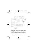
Connect the AC line power leads to terminals L1 and L2, or to
a double-throw, single-pole master power switch as shown in
Figure 4 on page 12 (recommended).
Line fuse connections
Wire an external line fuse between the stop switch (if installed)
and the L1 terminal as shown in Figure 4 on page 12. An
additional line fuse should be installed on L2 if the input
voltage is 230 VAC. The line fuse(s) should be rated at 250
volts and 150 - 200% of maximum motor nameplate current.
Refer to the line fuse chart on page 9 for fuse ratings.
Field output connections
Use 18 AWG wire to connect the field output to a shunt wound
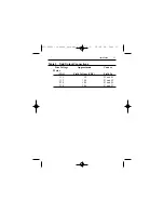
motor as shown in Figure 4 on page 12. See Table 2 for
alternate field output connections.
250-0089r3_readers_spreads.qxd 7/3/01 10:48 AM Page 10


