background image

1

SERVICE MANUAL

Electro-Pneumatic Regulator


MAER200 series

To ensure safe operation, please read this service manual carefully before use. When designing and 

manufacturing equipment using Mindman products, the manufacturer is obligated to ensure that the 

safety of the mechanism, pneumatic control circuit and/or air control circuit and the system that runs 

the electrical controls are secured.

Explanation of label

Observe the warnings and cautions on the following pages to prevent accidents. These instructions 

indicate the level of potential hazard by labels of "

WARNING

" or “

CAUTION

”. Note that some items 

indicated with “

CAUTION

” may lead to serious results depending on the conditions. All items 

contain important information and must be observed.

2021/12

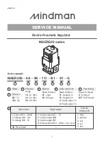
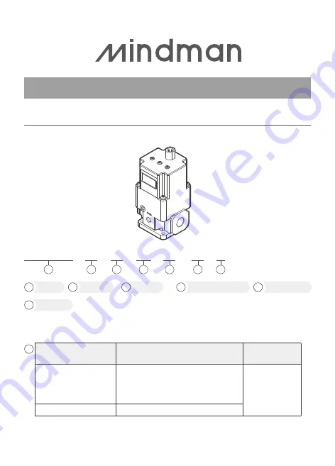
Order example

Model

MAER200 

 8A 

 9K 

 111 

 B1 

  S1 

 G

1

1

Port size

8A

: 1/4

10A

: 3/8

2

Pressure 

range

1K

: 0.1 MPa

5K

: 0.5 MPa

9K

: 0.9 MPa

3

Bracket
Blank: Without

B1

: L type

B2

: Flat type

5

Cable connector
Blank: Without

S1

: Straight 1m

S3

: Straight 3m

L1

: Right angle 1m

L3

: Right angle 3m

6

Port thread

Blank: Rc thread

G

: G thread

NPT

: NPT thread

7

2

3

4

5

6

7

1

: Current DC4~20mA

2

: Voltage DC0~10V

3

: Voltage DC0~5V

1

: Analog output DC1~5V

2

: Switch output NPN

3

: Switch output PNP

4

: Analog output DC4~20mA 

( Source type )

40

: Preset input

1

: MPa

2

: kgf/cm2

3

: bar

4

: psi

5

: kPa

Signal input

Signal output

Pressure

display unit

4

Summary of Contents for MAER200 Series

Page 1: ...lat type 5 Cable connector Blank Without S1 Straight 1m S3 Straight 3m L1 Right angle 1m L3 Right angle 3m 6 Port thread Blank Rc thread G G thread NPT NPT thread 7 2 3 4 5 6 7 1 Current DC4 20mA 2 Vo...

Page 2: ...t be operated by the person who has professional knowledge and practical experience Please confirm product specifications before use Do not use input signal exceeding specifications This product could...

Page 3: ...ubricator on the supply side of this product the lubricated air might cause malfunction When lubrication of terminal equipment is necessary connect a lubricator on the output side of the equipment and...

Page 4: ...nction Do not use power voltage exceeding specifications The product could malfunction or catch fire if voltage exceeding the working range is applied Short circuiting the load could result in rupture...

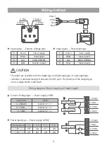
Page 5: ...e Blue Black 3 Blue 1 Brown 2 White 4 Black Current Voltage type Power supply 24VDC Preset input type Power supply 24VDC Input signal Model 4 20mADC MAER200 1 0 10VDC MAER200 2 0 5VDC MAER200 3 Preset...

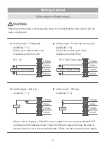
Page 6: ...5mA and then restart the power supply Wiring diagram Monitor output WARNING MAER200 2 MAER200 3 1 Brown 3 Blue 2 White 4 Black 1 Brown 3 Blue 2 White 4 Black Switch output NPN type Switch output PNP t...

Page 7: ...ressure Max pressure Switch output Preset pressure Gain Sensitivity Zero clear Reset setting Unit setting Display pressure Display unit Click Click Press Click Refer to P 9 Refer to P 10 12 Profession...

Page 8: ...or not specified it may cause direct burnout or malfunction Please confirm the specifications before use Please contact us when MAER do not operate normally after restarting the power supply 1 Check t...

Page 9: ...the keys In RUN mode press for more than 2 seconds Locking the key In RUN mode and unlocking press for more than 2 seconds and then press to return RUN mode Operation flow Operation flow 4 00 Loc vnL...

Page 10: ...ry doing an error ER4 will be indicated You must be return to set F_1 and F_2 F_1 is adjustable in range from 0 to 50 of the rated value DEFAULT VALUE 0 F_2 is adjustable in range from 10 to 100 of th...

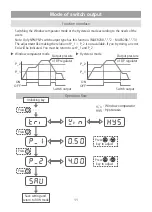
Page 11: ...is not available If you try doing an error Er4 will be indicated You must be return to set P_1 and P_2 Function introduce Window comparator mode Hysteresis mode P_2 P_1 Switch output Output pressure o...

Page 12: ...pressure range One of the preset pressures P_1 through P_4 is selected by the ON OFF combination of S1 and S2 Function introduce Preset pressure and switch Preset pressure P_1 P_2 P_3 P_4 S1 OFF ON OF...

Page 13: ...se refer to the following instructions to operate Function introduce Save setting and return to RUN mode Press key to switch the setting item Press key for 2 seconds or more Unlocking key Gn 5b 0 rSt...

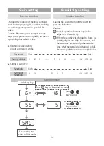
Page 14: ...f Gain 1 2 3 7 8 9 14 15 16 Function introduce Sensitivity High Low Setting of Sensitivity 1 2 5 6 7 14 15 16 Change the sensitivity Sb of the MAER for pressure fluctuation Caution Normal operation do...

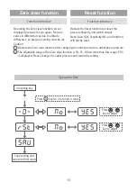
Page 15: ...ng the outlet pressure to atmosphere pressure The adjustable range of the Zero clear function is 5 F S When more than this range ER5 is displayed Please change the outlet pressure and return the setti...

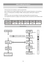
Page 16: ...ng refer to page 10 Caution The pressure unit is set according to the order specification before leaving the factory If you operate the function to change unit the product will be inconsistent with th...

Reviews: