background image

23


[


F-93


]

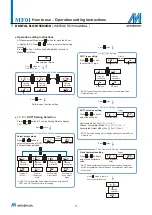
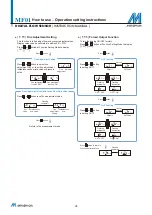
 Modbus RTU Setting

  MODBUS transmission protocol can be set according to user 

requirements.

  Press   or   button at Function Setting Mode to display  

F-93 

] [ 

AbUS 

].

* NOTE: This function only available for Output Specification -02 and -04.

* NOTE: This function only available for Output Specification -02 and -04.

DIGITAL FLOW SENSOR 

( INSTRUCTION MANUAL )

MF01 

How to use 

 Operation setting instructions

ID Number

Set Value

Press 


button

Flashing

alternately

Press   or   button 
to set ID number.

    1d

      1

ID number 0

ID number 1

ID number 255

      0

      1

  255

Flashing

alternately

Flashing

alternately

Flashing

alternately

Function Selection Mode

    1d

    1d

    1d

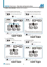
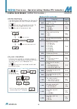
Baud Rate

Set Value

Press 


button

Flashing

alternately

Baud Rate Setting

Press   or   button 
to set baud rate.

  rRt

    96

9600 Bd

19200 Bd

38400 Bd

  rRt

  rRt

  rRt

    96

Flashing

alternately

Flashing

alternately

Flashing

alternately

  192

  384

* NOTE: This function only available for Output Specification -02 and -04.

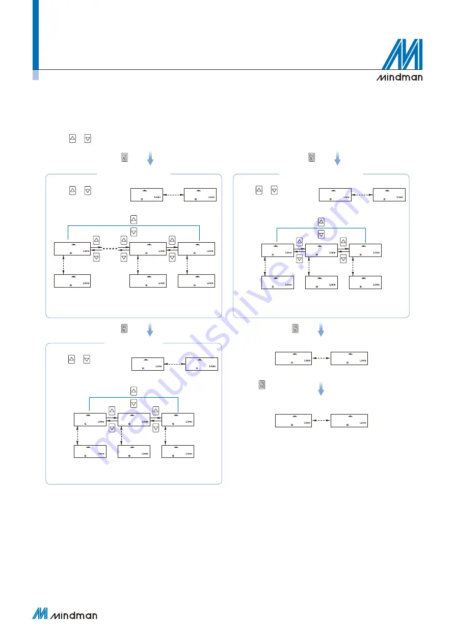
Transmission

Format

Set Value

Press 


button

Flashing

alternately

Press 


button

Transmission Format Setting

Press   or   button 
to set transmission 

format.

  For

  n81

n81

Even Parity

Odd Parity

  For

  For

  For

  n81

Flashing

alternately

Flashing

alternately

Flashing

alternately

  EUE

  odd

Flashing

alternately

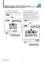
RTU mode

Press 


button to return to

Function Selection Mode

Flashing

alternately

F-93

  trA

  rtU

AbUS

Summary of Contents for MF01 Series

Page 1: ...Digital Flow Sensor MF01 series INSTRUCTION MANUAL 201012...

Page 2: ...7 F 02 OUT2 setting selection 18 F 03 LCD display color selection 19 F 04 Response time selection 19 F 05 Display refresh time selection 20 F 06 Unit selection 20 F 07 Flow reference standard selectio...

Page 3: ...ntaneous flow value Accumulated flow value NPN output PNP output Voltage output 1 5V Current output 4 20 mA 50 ms pulse output DIGITAL FLOW SENSOR INSTRUCTION MANUAL MF01 Product features Cost Control...

Page 4: ...ly inverted To set and watch monitor easily Accumulated flow rate display at a glance Accumulated flow rate display Flow rate L min MF01 005 MF01 010 MF01 050 MF01 100 MF01 500 MF01 101 MF01 201 Wide...

Page 5: ...pplication Application 01 Paint and coating flow monitoring Air flow and pressure management of paint and coating processes Application 02 Laser welding monitoring Precision management of shielding ga...

Page 6: ...n state of micro electronic parts by flow rate Application 05 Leakage detect Container with gas and inspect whether it leaks Application 04 Electronic part installation Control the tension of gold wir...

Page 7: ...from the heater spreads evenly left and right so the temperature distribution is like a b Small flow When flow begins the inlet side is cooled by the flow the outlet side is warmed by the heat of the...

Page 8: ...on Yes Accumulated pulse output 1 5 mL Pulse 10 mL Pulse 0 05 L Pulse 0 1 L Pulse 0 5 L Pulse 1 L Pulse 2 L Pulse 0 02 ft3 Pulse 0 04 ft3 Pulse 0 2 ft3 Pulse 0 4 ft3 Pulse 2 ft3 Pulse 4 ft3 Pulse 7 ft...

Page 9: ...ode Accumulated Output Mode Accumulated Output Mode Accumulated Pulse Output Mode Window Comparator Mode Hysteresis Mode Normal close mode NOTE 1 In case hysteresis is set at less than or equal to 2 d...

Page 10: ...s kPa Flow rate L min 1 2 3 4 5 0 08 0 07 0 06 0 05 0 04 0 03 0 02 0 01 0 0 1 MPa 0 2 0 3 0 35 0 4 0 5 Pressure loss kPa Flow rate L min 10 20 30 40 50 5 4 3 2 1 0 0 1 MPa 0 2 0 3 0 35 0 4 0 5 Pressur...

Page 11: ...to the product Piping for the One Touch Fitting insert the tube firmly into the fitting and make sure it cannot be pulled out Also using the proper tube cutter is recommended to ensure square edge tu...

Page 12: ...utput 2 Blue Power supply Orange Analog output Brown Power supply Main Circuit Load Load Orange RS 485 B Yellow RS 485 A Black Output 1 White Output 2 Blue Power supply Brown Power supply Main Circuit...

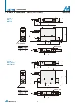
Page 13: ...al Thread Rc1 4 Rc1 8 Quick fitting 6 8 2 2 5 5 5 depth 2 2 5 5 5 depth 36 7 36 7 9 5 9 5 18 28 28 18 55 55 24 24 3 3 8 50 2 50 2 17 17 52 52 A B Code Tube I D A mm 8 92 2 6 83 Code Thread B mm Rc1 8...

Page 14: ...TRUCTION MANUAL MF01 Mounting accessories Mounting bracket Panel type MP A26 BT 26 Front protective lid Panel adapter MP C4 PA H Panel thickness 1 4 5 Front protective lid Panel adapter Panel adapter...

Page 15: ...ate directly Piping Port Outlet side Button Use for mode selection ON OFF switching and set value adjustment Setting Button Use for selection each mode and set value confirmation 4 Digit LCD Flow Disp...

Page 16: ...rial 1 Case PC ABS 2 Electronic circuit board 3 Sensor SiC 4 Liquid crystal cover PC 5 Liquid crystal 6 Button Silicone 7 Port filter Stainless steel 10 12 Port size F1C Rc1 8 F4C Rc1 4 Port size R6 6...

Page 17: ...et value input 60 of maximum measured flow rate 005 300 mL min 010 600 mL min 050 3 00 L min 100 6 00 L min 500 30 0 L min 101 60 0 L min 201 120 L min F 03 CLor LCD display setting CLor Select back l...

Page 18: ...etting 1 rAt Baud rate setting 96 9600 Bd For Transmission format setting n81 trR Communications protocol setting rtU F 94 F1nE Fine adjustment setting F1nE The displayed value can be adjusted slightl...

Page 19: ...tely Flashing alternately Flashing alternately Flashing alternately Function Selection Mode Output Mode Setting Set Value Setting Fixed Hysteresis Setting Output Type Setting Select output mode Press...

Page 20: ...button to select output mode of OUT2 3 output modes included OUT2 set value setting Press or button to adjust the set value Fixed hysteresis setting Press or button to adjust fixed hysteresis value Hy...

Page 21: ...splay color of OUT2 800ms 1500ms 400ms Flashing alternately Flashing alternately DIGITAL FLOW SENSOR INSTRUCTION MANUAL MF01 How to use Operation setting instructions Display Color Mode Selected Mode...

Page 22: ...ng Mode to display F 08 rotA Flow Sensor Flow Reference Display Rotation Set Unit Selected Condition Set Value Press button Press button Press button Flashing alternately Flashing alternately Flashing...

Page 23: ...Selection Mode DIGITAL FLOW SENSOR INSTRUCTION MANUAL MF01 How to use Operation setting instructions F 10 Flow Sensor Display Mode Selection Select to display Instantaneous Flow or Accumulated Flow Mo...

Page 24: ...ut please connect the input wire to GND for 30 ms or more Press or button at Function Setting Mode to display F 92 1nP Power Save Mode Selected Mode Press button Flashing alternately Power Save Mode S...

Page 25: ...g alternately Flashing alternately Function Selection Mode 1d 1d 1d Baud Rate Set Value Press button Flashing alternately Baud Rate Setting Press or button to set baud rate rRt 96 9600 Bd 19200 Bd 384...

Page 26: ...us flow value Fine adjustment setting Instantaneous flow DIGITAL FLOW SENSOR INSTRUCTION MANUAL MF01 How to use Operation setting instructions nE o Ff F1 nE oFf F1 O OO 0 St f SC F nE on F1 Press butt...

Page 27: ...ow value display mode until display 00 And release holding the button to return measurement mode Reset Accumulated Flow Function Accumulate flow value return to zero Operation Press and button simulta...

Page 28: ...LoC LoC LoC LoC off off on NOTE If a button operation is performed while the key lock setting is ON LoC will displayed Error code Explanation Operation 0000H ID Number 0 255 Range 0 255 Read Write 00...

Page 29: ...type 0 N O mode 1 N C mode Read Write 001AH Flow setting value FL 2 Read Write 001BH Flow setting value FH 2 Read Write Error code Explanation Operation 001CH Flow setting value ADL2 Read Write 001DH...

Page 30: ...orm the zero clear function again under no flow conditions System error Er4 Memory error Turn power off and then restart If error condition remains please return to factory for inspection Er5 Internal...

Page 31: ...cy induction furnaces and motors etc can generate high surge voltages if using near the sensor will cause the internal circuit components to deteriorate and cause damages 3 Sensors can not withstand l...

Page 32: ...o 3 when the piping is removed or replaced 2 Do not insert a stick or wire into the piping ports 3 Do not touch the terminals or connectors when power is on 4 Please do not replace fittings by yoursel...

Reviews: