background image

Operator’s Manual

16 - 1

16

Probes and Biopsy

NOTE:

For details of storage times and conditions for disinfected probes and brackets, refer to the Technical 
standard for Disinfection of Medical and Health Structures.

16.1 Probes

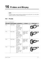
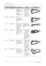
Table  16-1 Available probes 

Probe Mode Region Applied

Intended Use

Remark

Probe Figure

C4-1s

Body surface

Abdomen, 
Gynecology, 
Obstetrics, 
Cardiac, Vascular, 
Thoracic/Pleural, 
Urology, Small 
Parts

/

C5-1s

Body surface

Abdomen, 
Gynecology, 
Obstetrics, 
Vascular, Nerve, 
Musculo-skeletal, 
Urology, Thoracic/
Pleural, Small 
Parts

Supports contrast 
imaging under 
Abdomen exam 
mode.

C5-2s

Body surface

Abdomen, 
Gynecology, 
Obstetrics, 
Vascular, 
Pediatrics, 
Thoracic/Pleural, 
Urology, Small 
Parts

Supports contrast 
imaging under 
Abdomen exam 
mode.

C6-2s

Body surface

Abdomen, 
Gynecology, 
Obstetrics, 
Vascular, 
Thoracic/Pleural, 
Urology, Small 
Parts

Supports contrast 
imaging under 
Abdomen exam 
mode.

Summary of Contents for Ana

Page 1: ...us7 Zeus ME7 ME7 Exp Anesus ME7 Anesus ME7 Pro Anesus ME7S Anesus ME7T Ana Anesus Vaus Anesus Zeus Crius ME7P Crius ME7W Anesus ME7P Anesus ME7W Emerus ME7P Emerus ME7W MX7P MX7W Diagnostic Ultrasound...

Page 2: ......

Page 3: ...countries All other trademarks that appear in this manual are used only for informational or editorial purposes They are the property of their respective owners Responsibility on the Manufacturer Part...

Page 4: ...Malfunction or damage caused by improper operation or repair by unqualified or unauthorized service people Malfunction of the instrument or part whose serial number is not legible enough Others not ca...

Page 5: ...u shall also be continuously alert to dangers other than those indicated Mindray shall not be liable for damage or loss resulting from negligence or ignorance of the precautions and operating instruct...

Page 6: ...ettings and optional configuration the actual interfaces may be different from those in this manual Conventions In this manual the following conventions are used to describe the buttons on the control...

Page 7: ...ety Classifications 2 1 2 4 Product Specifications 2 2 2 4 1 Imaging Mode 2 2 2 4 2 Power supply 2 2 2 4 3 Environmental Conditions 2 2 2 4 4 Dimensions and Weight 2 3 2 5 Product Differences 2 3 2 6...

Page 8: ...r Brightness Contrast Adjustment 3 5 3 5 Connecting Disconnecting a Probe 3 6 3 5 1 Connecting a Probe 3 6 3 5 2 Disconnecting a probe 3 7 3 6 Connecting USB Devices 3 7 3 7 Connecting the Footswitch...

Page 9: ...eGateway Preset 4 43 4 9 Print Preset 4 44 4 9 1 Print Setting 4 45 4 9 2 Image Settings 4 45 4 10 Maintenance 4 45 4 10 1 Option 4 45 4 10 2 Exporting Setup Data 4 46 4 10 3 Importing Setup Data 4 46...

Page 10: ...6 8 1 PW CW Mode Image Scanning 6 14 6 8 2 PW CW Mode Image Parameter 6 14 6 9 iScape 6 17 6 9 1 Basic Procedures for iScape Imaging 6 17 6 9 2 Image Review 6 18 6 9 3 Evaluate image quality 6 18 6 9...

Page 11: ...ging 9 2 9 4 Image Parameters 9 2 9 5 Image Saving 9 4 9 6 Micro Flow Enhancement 9 4 9 7 Contrast Imaging QA 9 4 10 Physiological Unit Signal 10 1 10 1 ECG 10 1 10 2 Respiratory Wave 10 3 10 3 ECG Re...

Page 12: ...2 13 2 1 Adding Comments 13 3 13 2 2 Moving Comments 13 4 13 2 3 Editing Comments 13 4 13 2 4 Deleting Comments 13 4 13 2 5 Setting the Start Position 13 5 13 3 Body Mark 13 5 13 3 1 Adding Body Mark...

Page 13: ...ter sending images on the iStation screen 15 5 15 5 2 To send storage commitment automatically after an exam ends 15 5 15 6 Query Retrieve 15 5 15 7 DICOM Media Storage DICOMDIR Review 15 6 15 7 1 Med...

Page 14: ...18 1 3 Cleaning the peripherals 18 6 18 1 4 Checking the Probe 18 6 18 1 5 Checking the Power Cable and Plug 18 7 18 1 6 Checking Appearance 18 7 18 1 7 System Hard Drive Backup 18 7 18 2 Troubleshoot...

Page 15: ...2 D 3 EAP Network D 3 E iScanHelper E 1 E 1 Use iScanHelper for Reference E 1 E 2 Use iScanHelper for Learning or Training E 1 E 3 Basic Screen and Operation E 2 E 3 1 View Selecting Area E 2 E 3 2 S...

Page 16: ...c Output Parameters H 4 H 7 2 Limits of Acoustic Output H 5 H 7 3 Differences between Actual and Displayed MI and TI H 5 H 8 Measurement Uncertainty H 6 H 9 References for Acoustic Power and Safety H...

Page 17: ...ic shock may result Do connect the power plug of this system to wall receptacles that meet the ratings indicated on the rating nameplate If adapters or multi functional receptacles are used it may cau...

Page 18: ...may result or a gas explosion may occur Before cleaning the system disconnect the power cord from the outlet System failure and electric shock may result This system is not water proof designed Do Not...

Page 19: ...your vendor Prolonged and repeated use of keyboards may result in hand or arm nerve disorders for some individuals Observe the local safety or health regulations concerning the use of keyboards When u...

Page 20: ...iod of time required for the purpose of diagnosis Do not use the system to examine a fetus for a long period of time Except accessories that have been stated as sterile the system and its accessories...

Page 21: ...tions with high humidity Turn ON the system only after the power has been turned OFF for a while If the system is turned ON immediately after being turned OFF the system may not be rebooted properly a...

Page 22: ...each examination A defective probe may cause electric shock to the patient Do not subject the probe to shock A defective probe may cause electric shock to the patient Do not disassemble the probe to a...

Page 23: ...t of improper gel or cleaner DO NOT dip the transducer in the strong polar solution of ethanol chloride of lime ammonium chloride acetone and formaldehyde DO NOT contact the transducer with solution o...

Page 24: ...EE label applies to EU member states only The use of this symbol indicates that this system should not be treated as household waste By ensuring that this system is disposed of correctly you will help...

Page 25: ...s rated as IPX8 The power adapter is rated as IP22 According to the disinfection and sterilization method s recommended by manufacturer Equipment with disinfection and sterilization method s recommend...

Page 26: ...tery voltage 14 4 V 2 4 3 Environmental Conditions Operating conditions Ambient temperature 0 C 40 C Relative humidity 20 85 no condensation Atmospheric pressure 700 hPa 1060 hPa Storage and transport...

Page 27: ...ions and Weight Dimensions D W H unit mm 322 5 364 5 44 3 Weight including batteries 4 0 kg 2 5 Product Differences Model Histogram Profile Color Vel Double Dist Spline length Parallel line MX7 MX7 Ex...

Page 28: ...defined label Cables 2 6 2 Probes and Needle guided Brackets Available Please see 16 Probes and Biopsy 2 6 3 Options MX7W Model Histogram Profile Color Vel Double Dist Spline length Parallel line Item...

Page 29: ...t Cardiology Package should be configured Strain Elastography Stress Echo Cardiology Package should be configured Tissue Tracking QA Cardiology Package should be configured Smart 3D DICOM DICOM Basic...

Page 30: ...erve Package Emergency Critical Package RIMT Vascular Package should be configured AutoEF Cardiology Package should be configured R VQS Vascular Package should be configured Smart B line Smart VTI Car...

Page 31: ...system is connected to Class B peripheral devices otherwise RF interference may occur and the customer or user must take adequate measures accordingly 2 6 5 Parts that can be used within patient envi...

Page 32: ...on Power indicator Used for turning on off the power The indicator lights up when the system is powered on 4 S Video S Video signal output 5 Network port Connects to network 6 HDMI Used for extending...

Page 33: ...the actual buttons and knobs 11 Probe port Connects a probe to the main unit or connects a probe extend module 12 Probe locking lever Locks or unlocks the probe connected with the main unit locked sym...

Page 34: ...types of screws After fixing the module using handle screws fold the handles parallel to the bottom of the main unit 1 Insert the connector to the probe port of the main unit 2 Toggle the locking lev...

Page 35: ...he U Bank installation and uninstallation If you need to change the batteries in the U Bank please contact your sales representative Specifications are as follows Voltage 19V DC Capacity 26400 mAh or...

Page 36: ...blinks remaining capacity 20 5 Baterry status indicator Indicates the charge discharge status of the U Bank When the battery is charging Not fully charged the indicator blinks in orange Fully charged...

Page 37: ...re above until the system is locked in place TIP To remove the U Bank from the system press the detach lever of U Bank and lift up slightly the system by holding the system s handle 2 10 ECG Module Ov...

Page 38: ...gured with trackpad 2 ECG lead port Used for ECG signal input No Name Description No Name English Name Description 1 TDI TDI mode button Enters TDI mode P4 User defined key Undefined button set by the...

Page 39: ...ual split window button Press to enter the Dual mode from another mode Press to switch between the two windows in the Dual mode 12 Image zoom Press to enter or exit zoom status 13 iTouch Gain Gain and...

Page 40: ...lluminates in green color when the power of the batteries is sufficient It illuminates in orange color for low battery power 21 Clear Clear button Press to clear off the comments or measurement calipe...

Page 41: ...ion screen 3 Probe exam mode switch button Tap to switch probe and exam mode 4 Scan button Tap to enter B imaging mode 5 Patient data management system button Tap to enter or exit patient information...

Page 42: ...ment calipers color bar grayscale bar are also displayed here 4 Hint trackball trackpad and Set key function indications Displays the current functions of trackball trackpad and Set keys 5 User define...

Page 43: ...ation and close the screen To reposition a dialog box 1 Use the trackball trackpad to move the cursor onto the title bar of the dialog box At this time the cursor becomes a then press Set key 2 Use th...

Page 44: ...Parameter magnitude setting Tap the left right part of the parameter button or tap to select the parameter button and rotate the multi functional knob to increase decrease the value ON OFF setting so...

Page 45: ...ter bodymark status 3 Comment tab Tap to enter text arrow comment status 4 Page If there is more than one page of comment texts for the current exam mode you can slide to view more 5 Comment position...

Page 46: ...Panel 12 Language button 13 Arrow button Tap to add an arrow comment to the image 14 Library Tap to pop up and select the library No Item Description Function Operations Adding a control Tap to select...

Page 47: ...microphone the system recognizes the vocal order The system conducts the operations after recognizing the voice 2 Click to stop the voice Recognition 3 Click to open the help information No Warning La...

Page 48: ...ator Battery indicator When the lever located at the bottom of the monitor support arm points to you can move the monitor to the right and left When the lever located at the bottom of the monitor supp...

Page 49: ...roduct is provided with a CE marking in accordance with the regulations stated in Council Directive 93 42 EEC concerning Medical Devices The number adjacent to the CE marking 0123 is the number of the...

Page 50: ...This page intentionally left blank...

Page 51: ...his system can work normally only when it is connected to the external power supply or the battery capacity is sufficient 3 2 1 Connecting Power 1 Connect the connector of the power adapter to the ada...

Page 52: ...permanently damaged Battery specification Voltage 14 4 V Capacity 6600 mAh single battery Battery Status Indicator The battery status indicator is located in the bottom right corner of the screen ind...

Page 53: ...e clean The locking mechanism of the casters if there is a trolley works normally 3 3 2 Power the System ON Press the power button to power the system on If access control has been set by the system a...

Page 54: ...inuous absent or black items in the B mode image Check whether there is abnormal heat on the surface of the probe during an ultrasound procedure If you use a probe which is giving off excessive heat i...

Page 55: ...e the batteries will be out of power and permanently damaged If the system will not be used for a long period of time you should disconnect the power adapter disconnect the mains power and turn off th...

Page 56: ...m falling off or becoming damaged Only use probes provided by Mindray Aftermarket probes may result in damage or cause a fire 3 5 1 Connecting a Probe WARNING The probes cables and connectors should b...

Page 57: ...sfully and the symbol appears in the bottom right corner of the screen To remove the USB device click to open the Remove USB Device screen Select the device to be removed and click OK A sound is heard...

Page 58: ...ord and data cable The power cord shall be directly connected to a wall receptacle as required Perform the following procedure 1 Connect the data cable to USB port of the ultrasound device 2 Power on...

Page 59: ...rget printer from the drop down list in the Property box and set other printing properties f Click OK to complete 3 8 3 Connecting a Wireless Printer The system supports the wireless graph text printe...

Page 60: ...This page intentionally left blank...

Page 61: ...en To exit Setup Select OK in the Setup menu The parameter settings are saved Select Cancel in the Setup menu to close the Setup menu When you change the system language and click OK in the Setup menu...

Page 62: ...s and 8 24 32 bitdepth Time Zone To select the time zone Time Format To select the time format Date Format To set the date format System Date To set the date for the system System Time Move the cursor...

Page 63: ...he DICOM server for storage print Send SR after End Exam Select whether to automatically send structure report to the DICOM server Maximum number of exams to be kept To set the maximum number of exams...

Page 64: ...settings back to factory IVOCAL Automatically shut down waiting time To set the delay before voice recording stops automatically Enable Voice Response After it is ticked the system will repeat record...

Page 65: ...e imaging mode B Color Refresh with PW CW Sampling Line Movement To set whether to turn on the function that when moving PW CW sampling line B Color image is activated under B Color PW CW mode Uninter...

Page 66: ...ze of the cursor Heart Beat The number of cardiac cycles in the heart rate calculation In heart rate measurement the number of cardiac cycles should match the preset number Cursor Line Display If unse...

Page 67: ...Fetal Growth or Fetal Weight page select an OB Item in the left column 2 Select a formula in the right column 3 Click Default The default formula is marked with a To set the fetal weight display Perf...

Page 68: ...95 10 90 Unit of the measurement value according to the table to import select from mm cm g kg cm or mm Row number N of the table the maximum row number N in the column No The third row is empty GA va...

Page 69: ...osis You can add user defined formulae for items obstetric tools that are not included in the GA and FG table 1 Select More OB Items on the Fetal Gestational Age or Fetal Growth page 2 Select an item...

Page 70: ...e steps above Trackball Speed Set the speed of the trackball when using the trackball Key Volume Set the key volume level Key Brightness Set the brightness for the keys Trackball Light Set the light c...

Page 71: ...ow the available auxiliary functions for current key Select Send Image to DICOM Storage in the Output column on the right side Then the Function 2 on the left side turns into Send Image to DICOM Stora...

Page 72: ...horized before accessing the data and you can configure password policy and LDAP and change password If unselected you can access all the data without authorization and you cannot configure password p...

Page 73: ...ed user Editing Privilege Turn on the access control function and log in to the system as Administrator before you edit privileges 1 Select a user click Edit Privilege to enter the Edit user privilege...

Page 74: ...t the duration after an account is locked Reset all lockout Reset all locked accounts Enable strong password Enable strong password to improve security If the strong password is enabled and you log in...

Page 75: ...rs and privileges will appear in the Member of filter list Select a member to be deleted and click Delete Select a member to be modified modify the member name and select or deselect privileges from t...

Page 76: ...set screen press Cursor to show the cursor and move the cursor to the bottom right corner of the screen Click icon to see the scene management list b Click Configure to see the following dialog box c...

Page 77: ...n Operator or Diagnostician item in Patient page automatically After scanning a 1D barcode of an operator or diagnostician for a second time the obtained data is B and A will be appended by B in Opera...

Page 78: ...y service engineer Item Description Item Description Scan Barcode Example Input a barcode example barcode example is separated by separators the separator is used to set the start and end position of...

Page 79: ...add all exam modes in the library to the Probe and Exam Mode list Click add all probe and exam modes in the library to the Exam Mode Library list Click Delete to delete a user defined exam in the Exa...

Page 80: ...Select the 2D M or Doppler tab to go to the corresponding preset menu Available Items general measurement tools configured by the system in the current scanning mode which are available but not assign...

Page 81: ...tion Item Name Result Results obtained from D trace are listed The selected items will be displayed in the results window after measurement If PV is selected other results become deselected except the...

Page 82: ...ting Package Positions Creating Packages Click New and enter a name for the new package in the dialog box pop up Click OK to confirm the new package displays in the Available Items list Adding Removin...

Page 83: ...gonometric functions are in degrees not radians PI is accurate to 7 digits Adding B Hist or B Profile to the study is not supported Click Export Custom in the measurement preset window to export the u...

Page 84: ...a Select User Defined in the Available Items and select the desired item b Click Delete Remove Study Select a user defined study click 4 3 3 Report Preset NOTE Deleting is not supported in IVF IMT and...

Page 85: ...g and exit 7 Change the patient information layout in the report template Change the template used in the report layout click New Layout to select another template Double click the information lines t...

Page 86: ...displayed below Available Items 2 Click and to add the item in Available Items on the left into Selected Items on the right TIP You can only delete the user defined items rather than the items in the...

Page 87: ...can customize the protocols and views in the iWorks preset screen 4 5 1 Protocol Management Click to select the protocol in the list The protocol type can be checked on the right Click Add Protocol to...

Page 88: ...tocol Or select an existing protocol and click Copy to customize the protocol based on the previous template 2 Enter the protocol name type and select the application region 3 Click Add View to enter...

Page 89: ...e list b Enter a phase name Select Auto Select the system jumps to Select Mode after retrospective acquisition Item Description Protocol Name Enter the protocol name Trigger Set the trigger type WMS m...

Page 90: ...protocol Deleting a Stress Echo Protocol Click an user defined protocol on the Select Protocol screen click Delete Protocol 4 6 2 Maintenance Item Description Acquire mode Set the type of ROI manual R...

Page 91: ...value is less than 16384 or greater than 65536 the system automatically sets it to the value 32768 DICOM output charasets Select an character set for DICOM output according to the local PACS workstat...

Page 92: ...e from the Strategy List and assign strategy items to the selected strategy Add Set the function from the drop list box enter the parameter 1 and parameter 2 and click Add Then the added strategy item...

Page 93: ...correct application name Storage Service Preset DICOM storage preset items are described as follows Item Description Device After you set the server s in DICOM Preset screen the name s will appear in...

Page 94: ...when choosing the mix The image use 8 bit if the image is captured in color mode or the image has the tint All images use 8 bit when choosing the grey Allow Multiframe If SCP supports this function th...

Page 95: ...nd white printing Please select the type the printer supports Film Orientation Select between LANDSCAPE and PORTRAIT Priority Specify printing task priority among HIGH MED and LOW Film Size Select fil...

Page 96: ...the service TLS Transport Layer Security Select whether to encrypt the data during network transportation Strategy Name Set the DICOM strategy Remove Attributes 0 Set what DICOM element s that will no...

Page 97: ...me s Reserved feature Timeout Refers to the amount of time after which the system will stop trying to establish a connection to the service Associated Storage Service The associated storage server is...

Page 98: ...y title here it should be consistent with that of the HL7 server Port DICOM communication port 104 by default Here the port should be consistent with that of the HL7 server port Maximum Retries Reserv...

Page 99: ...N is successfully connected Disconnected VPN is disconnected Error error connection Server IP Group User Name Password Hide characters The password is displayed as Connect Disconnect Connect or discon...

Page 100: ...vice to be updated in the service list 2 You can see properties in the Configure Service area 3 Do one of the following to edit the network service Modify the properties and click Update to update the...

Page 101: ...twork website service you can check data using the website authorized account and password provided by the service vendor You can open the browser Q View to review previously sent DICOM data Q path is...

Page 102: ...rver Password On Worksheet Sets whether to display the Signature field box in a worksheet Tap Report WorkSheet or tap Review Report WorkSheet enter the worksheet password in the field box and click OK...

Page 103: ...eway service 1 Set the eGateway server properties as described above 2 Tap Add to add the service to the service list To modify a network service 1 Select the service to be updated in the service list...

Page 104: ...t Port for transmitting DocServer IP Address IP address of the eGateway service Port Port for transmitting Image Cine PDF Report Set the shared document content Clear Click to cancel the parameter set...

Page 105: ...ire other maintenance functions please contact Mindray Customer Service Department or sales representative 4 10 1 Option The system enters the Option page after entering the Maintenance screen In the...

Page 106: ...em The system will reset and operate according to the setup preferences that were imported Perform the following procedure 1 Click Import to open the Load Data screen 2 Select the imported file 3 Clic...

Page 107: ...eSpacial Navi function NOTE The list of needles must be release version provided by Mindray Needles List Recover Restore the list of needles that support eSpacial Navi function to the last version Ne...

Page 108: ...b Click Wipe and operate according to the screen prompts to clear patient data c Select User Define again and click Confirm d Input the password and click Confirm to finish the password setting NOTE...

Page 109: ...exe or any other abnormal operation during the installation please contact the Mindray service engineers Transmission Encryption After accessing the network click VPN Config to enter the VPN Config in...

Page 110: ...This page intentionally left blank...

Page 111: ...a new patient exam it is better to type the detailed patient information The system will set up a unique information database for each patient based on the patient information entered so that the inf...

Page 112: ...al causes or system power off Cancel Exam to cancel the current exam The cancelled exam can t be restored Click Quick Register to save the patient information quickly and return to the main screen OK...

Page 113: ...the new exam simultaneously After editing the patient information in the Patient Info screen select OK to start a new exam Review Image Click to enter the Review screen Patient Infor Click to enter th...

Page 114: ...ted exam you can modify patient ID 5 2 2 Continue an Exam In iStation screen select an exam record paused within 24 hours click Resume Exam from the menu popped up to continue the exam If you want to...

Page 115: ...on to avoid mixing data of the next new patient To end an exam do one of the following Tap End on the touch screen to finish the current exam Click New Patient on the Patient Info screen to end the la...

Page 116: ...This page intentionally left blank...

Page 117: ...B to return B mode Adjust parameters to optimize the image 6 1 2 B mode Image Parameters Image Quality Used for switching B THI and adjusting the frequency The real time value of frequency is displaye...

Page 118: ...is available only for the convex and phased probes When the scan range is adjusted to the widest the FOV position cannot be changed Steer To steer the beam the probe transmits TIP Steer is available...

Page 119: ...image Tint Map This function provides an imaging process based on color difference rather than gray distinction TSI The TSI function is used to optimize the image by selecting acoustic speed according...

Page 120: ...ates the flow towards the probe while the color below the color bar indicates the flow away from the probe the brighter the color is the faster the flow speed becomes while the darker the color is the...

Page 121: ...et Size This function is an indication of the ability to detect flow which is used to adjust the accuracy of color flow The higher the sensitivity is the more sensitive indication for low velocity flo...

Page 122: ...evels of the flow display to display the grayscale signal or color signal The color image is preferred with higher value while grayscale signals are displayed with the lower value Velocity Tag This fu...

Page 123: ...ow velocity flows The Directional Power maps provide information of flow direction Dynamic Range This function is to adjust the transformation of echo intensity into color signal Increasing dynamic ra...

Page 124: ...W and Power See the relevant sections for details The following introduces the specific items in TDI mode Tissue State This function is used for fast image optimization 6 4 3 TDI Quantitative Analysis...

Page 125: ...the trackball trackpad the images in TDI review window and 2D review window are reviewed synchronously since the two images are frozen at the same time ROI movement is linked between the TDI Tissue D...

Page 126: ...lete the drawing Press Clear to cancel the active ROI 4 Select the curve Tap Speed Strain or Strain Rate For Strain or Strain Rate tap Strain Dist on the touch screen to select the corresponding value...

Page 127: ...de image the real time gain value is displayed in the image parameter area Increasing the gain will brighten the image and you can see more received signals However noise may also be increased Display...

Page 128: ...determine the size and position of the color flow displayed in the color M mode image 6 7 Anatomical M Mode For an image in the traditional M mode the M mark line goes along the beams transmitted fro...

Page 129: ...Press B to return to real time B mode 6 7 2 Free Xros CM Curved Anatomical M Mode In Free Xros CM mode the distance time curve is generated from the sample line manually depicted anywhere on the imag...

Page 130: ...time while the vertical axis represents Doppler frequency shift PW mode provides a function to examine flow at one specific site for its velocity direction and features while CW mode proves to be much...

Page 131: ...e parameters as per the current tissue characteristics for a better image effect Auto Calculation This function is used to trace the spectrum and calculate the PW CW mode image parameters The results...

Page 132: ...Doppler scale or when the selected anatomical site is too deep for the selective PW Doppler scale Baseline Refers to the area where the velocity in zero in the spectrum The map changes after being ed...

Page 133: ...o become fully proficient Therefore the measurement results can be inaccurate Exercise caution when you perform measurements in iScape mode A smooth and even speed will help produce optimal image resu...

Page 134: ...capture Tap Stop Capture on the touch screen Press Update Wait until the acquisition completes automatically After the acquisition is completed the panoramic image will be displayed and the system en...

Page 135: ...on arterial stiffness tracks movements of the upper and lower vessel walls and measures vessel diameter displacement coefficient of hardness and PWV dimensionless pulse wave velocity Hardness coeffici...

Page 136: ...ame Tap Accept Result to update the result window data to the report Save the single frame and multi frame image if necessary Tap Cancel Result to recalculate RIMT and perform step 3 5 if necessary 7...

Page 137: ...Scanning Areas to select different zone combinations for examination 4 Select a desired zone and tap Auto Calc The system automatically starts tracing the B line sampling area and automatically recog...

Page 138: ...b to select items 6 Press the Save key to save the single frame image and B line calculation results If necessary press the Freeze key again to unfreeze the image Repeat steps 4 6 to finish calculatin...

Page 139: ...tting the starting point for measurement and Update to switch the active end and fixed end of the caliper d Press Set to set the end point For more information about measurement see Advanced Volume 4...

Page 140: ...s can be saved and displayed 6 13 Smart IVC Smart IVC is used to automatically measure the IVC inner diameter and calculate the change rate in the B mode image Measure the IVC Inferior Vena Cava in re...

Page 141: ...ll trackpad to adjust the sampling line position c Press the Update key to start calculating IVC again 5 Press the Freeze key to freeze the image and finish calculating IVC The calculation results and...

Page 142: ...screen to select left or right carotid 3 Use the trackball trackpad to locate ROI over the target area The dotted line of the ROI is in the middle of the blood vessel Press Set to confirm the positio...

Page 143: ...arching method to trace each spot and calculate the movement so as to determine myocardial motion in a more quantitative way Tissue tracking quantitative analysis is an option NOTE Only use the probes...

Page 144: ...nner dots of the curve Move the cursor to the exact boundary position and press Set again to set the right place Tap Start Tracking to start tracking again 6 Tap Accept Compute to calculate and displa...

Page 145: ...no longer displays You can get the current X Y axis value by moving the cursor onto one point on the curve and if you press Set at this time the frame marker will move to the spot The segment boundar...

Page 146: ...3 point method As shown in the following figure after operation by pressing Set to place 3 points on the image the system generates the trace automatically Manual trace method Press Set and move the c...

Page 147: ...base section short axis view of mitral valve PSAX M short axis view of base section short axis view of papillary muscle PSAX AP short axis view of apex Parameter Adjustment Thickness adjusts the traci...

Page 148: ...he X axis represents time s the Y axis represents rotation of the tissue Deg Circumferential Rotation Rate curve The X axis represents time s the Y axis represents rotation by time Deg s Torsion Torsi...

Page 149: ...Tap iWorks on the touch screen or press the user defined key for iWorks to enter the protocol selection screen and tap the corresponding protocol button to enter the status After the system enters th...

Page 150: ...automated protocols of OB the touch screen displays as following 6 16 2 View Operation In iWorks status you can perform view selection repeat replacement and delete operations using the touch screen...

Page 151: ...xamination Suspend Exit the protocol so the user can run the system manually This is used when an unusual or atypical workflow is required You can run the system manually if necessary Start manual exa...

Page 152: ...e M mark line always appears after being set when entering PW M TVM mode for once Press PW M to enter the corresponding mode one time This function is unavailable for frozen dual probe mode 5 To save...

Page 153: ...However 3D imaging can obtain the reference information by overall observation 7 1 1 Terms Volume data to obtain the data collection of three dimensional object via the sequence reconstruction to two...

Page 154: ...truction Set ROI on the 2D image with the largest section area of the fetal face Set ROI a little larger than the fetal head Perform the following procedure 1 Press the right Set key to toggle among s...

Page 155: ...D image rendering mode Display the minimum echo intensity in the observation direction This is helpful for viewing vessels and hollow structures X Ray Set X ray as 3D image rendering mode Display the...

Page 156: ...provided for reference only not for confirming a diagnosis Please use caution to avoid misdiagnosis 7 1 5 Wire cage When you view a 3D image on the display monitor it s sometimes difficult to recogni...

Page 157: ...bilical cord The fetus keeps still If there is a fetal movement you need a rescan when the fetus is still Angle of a B tangent plane The optimum tangent plane to the fetal face 3D imaging is the sagit...

Page 158: ...The arrow in the figure below indicates the movement of the probe You can move the probe in the opposite direction to the arrow 7 2 1 Smart 3D Image Acquisition NOTE In Smart 3D image scanning if the...

Page 159: ...ode 7 2 2 Smart 3D Image Viewing Activate MPR Select Ref Image A B C or VR to activate sectional plane image MPR or 3D image VR MPR Viewing In actual display different colors of the window box and the...

Page 160: ...e system supports the observation of 3D image from 6 directions Tap Up Down Left Right or Front Back to select the direction of the figure a c and e Tap Flip on the first page to observe by the conver...

Page 161: ...viewing status you can render the image by adjusting the relevant parameters Tap VR or MPR on the touch screen to select the VR parameters or MPR parameters When VR button is highlighted adjust param...

Page 162: ...The color of image change according the tint value Quick Rotation Rotate the 3D image quickly iClear Use the 3D self adapation filter to strengthen the space continuity of the tissue structure and pr...

Page 163: ...Use the trackball trackpad to view to a certain position tap Set End d Set the auto rotation increment rotate the knob under the Increment e Tap Off to start auto rotation Use Speed to adjust the rota...

Page 164: ...Set to trace the region When the start point and the end point coincide the region is selected or you can press Set twice to finish tracing 3 Move the cursor to the region you want to edit and press S...

Page 165: ...rientation and press Set to start drawing press Set when ends are necessary press Set twice to finish drawing 3 Move the cursor to the region you want to edit and press Set again to edit Soft Eraser A...

Page 166: ...This page intentionally left blank...

Page 167: ...ap Elasto on the touch screen or press the user defined key for Elasto to enter the elastography mode The system displays two dual B E windows in real time The left one is 2D image and the right one i...

Page 168: ...down display the elasto image appears above and the real time ultrasound image appears below Full The elasto image only displayed Map Select different maps for observation Strain mode Affect the displ...

Page 169: ...st imaging is an option Select an appropriate probe for Contrast Imaging see 16 1 Probes 9 1 Basic Procedures for Contrast Imaging Perform the following procedure 1 Select an appropriate probe and per...

Page 170: ...nces echo reflection by using contrast agent to perform myocardial analysis based on echocardiography technique Perform the following procedure 1 Acquire ECG signal 2 Select an appropriate probe and c...

Page 171: ...time via the touch screen Dual Live In live mode or freeze mode set touch screen item Dual Live as ON to enable dual live function Both the contrast mode and tissue mode are displayed The THI and B im...

Page 172: ...Perform the following procedure 1 During real time scanning tap MFE on the touch screen to start MFE imaging 2 Use MFE Period on the touch screen to select different imaging period suitable for curre...

Page 173: ...ifferent color and its corresponding trace data is plotted using that same color 1 Contrast cineloop window Sample area indicates sampling position of the analysis curve The sample area is color coded...

Page 174: ...e for time intensity curve and perform data analysis on time intensity curve for data table Tap Raw Curve to hide display raw curve when the button is highlighted in green raw curve is displayed Tap T...

Page 175: ...Select the drive and enter the file name in the displayed window c Select OK to save the data and return to the QA Analysis screen All displayed ROI traces are saved in the exported file The parameter...

Page 176: ...This page intentionally left blank...

Page 177: ...place the ECG electrodes directly in contact the patient s heart otherwise it may lead to stop of the patient s heartbeat Do not apply the ECG electrodes if the voltage exceeds 15 volts This could pro...

Page 178: ...ime triggering delay time and image display format 6 Freeze the triggering image and the curve and then review them 7 Tap Physio or press the user defined key for Physio to exit ECG mode and remove EC...

Page 179: ...Real Trigger Tap Real Trigger to enable or disable the real trigger function After the Real Trigger is enabled two images are displayed respectively in two windows One is triggered by ECG and the oth...

Page 180: ...ime 10 4 Parameter Description The physio parameters are described as follows Parameter Description ECG Source Select ECG source Gain Set the amplitude of the trace Position Set the vertical position...

Page 181: ...s stages are limited by time rather than a maximum number of loops the system stops acquisition after two minutes Acquisition is prospective when you select the stage label and then press Save on the...

Page 182: ...m displays a percentage marker below the selected stage indicating the progress of the continuous capture To halt saving acquired images for the selected stage tap Pause on the touch screen or press F...

Page 183: ...w and zoom in the clip to the full screen Double click a clip The clip will be magnified Tap First Last or Previous Next on the touch screen to display another loop in the current view 3 Select the st...

Page 184: ...ect Display Selected on the touch screen The system displays the selected phases for each selected view side by side To display all views for a specific phase Select the phase label for example Rest T...

Page 185: ...and ASE 17 are supported In addition each segment has 3 kinds of scoring method 4 5 and 7 points Select through the Scoring control on the touch screen To assign a wall motion score WMS 1 Select a col...

Page 186: ...am 11 5 Exiting the Stress Echo Feature To exit the Stress Echo feature Tap End or End SE exam on the touch screen 11 6 Measurement and Report Suspend the stress echo exam by selecting Suspend Exam Pr...

Page 187: ...nsity to occur at a different location in the acoustic filed As a result the MI may change 12 2 1 Spot Zoom Perform the following procedure 1 Press Zoom to enter the sample volume definition status 2...

Page 188: ...key for Quad to switch among the windows press B to exit splitting display mode and enter the image of the currently activated window in full screen In frozen mode the system supports imaging mode swi...

Page 189: ...ckball trackpad the review sequence is reversed to the image storing sequence thus the images are displayed in descending order Whereas if you move the playback mark to the right by using the trackbal...

Page 190: ...en to set the review speed The system plays the auto review region automatically 4 Tap Jump to First Jump to Last to review the first or last image 12 4 3 Cine Review in M PW CW TVD Mode Enter cine re...

Page 191: ...Compare in Review Mode TIP For B B COLOR B TVI B POWER B TEI mode image you can select at most 4 images for PW M CW TVD mode image you can select at most 2 images Perform the following procedure 1 Tap...

Page 192: ...age windows cine replaying can t be performed for single frame image file press Update or Dual key to switch the active image window 3 Save the image if it is necessary Measurements adding comments an...

Page 193: ...choose the type of the saving time and the cardiac cycles Use Time Post or Cycle Post to adjust it Prospective Cine Length Retrospective cine duration set the time that user taps Retro when playing th...

Page 194: ...This page intentionally left blank...

Page 195: ...otherwise false readings and potential misdiagnosis may result CAUTION If an image is unfrozen or the mode is changed during a measurement the calipers and measurement data will be cleared from the s...

Page 196: ...or add the trace For products equipped with the trackpad set user defined keys for comments text arrow and trace first see 4 1 7 Key Configuration WARNING You must ensure that the entered comments ar...

Page 197: ...ow button or press the user defined key for Arrow to enter the arrow status 2 Adjust the position and orientation of the arrow Use the trackball trackpad to move the arrow to the desired position Rota...

Page 198: ...to move the cursor to the desired location to insert delete characters you can either type characters by pressing the corresponding keys or select the new comment text from the menu 2 Press Del to del...

Page 199: ...he system will clear all comments on the image Press the user defined key for Delete Text or long press Clear key to delete all the comments 13 2 5 Setting the Start Position Perform the following pro...

Page 200: ...between the separate image windows Perform the following procedure 1 Press Cursor and use the trackball trackpad to move the cursor onto the body mark The cursor then becomes indicating you can move...

Page 201: ...to external memory devices For a save image you can perform operations like image reviewing analyzing and demonstration 14 1 1 Storage Media System supported memory media including System hard disk US...

Page 202: ...o the system quickly Press the user defined key for Save Cine Retrospective Prospective to save the cine file in the default file directory in the CIN format The thumbnail of this image will appear in...

Page 203: ...d patient display at the bottom of the screen When you move the cursor onto a thumbnail its name and format will display On the Review page the thumbnails refer to the images stored in the same exam W...

Page 204: ...tus 2 To exit the image analysis Press Freeze to exit and enter the real time scan status Press Return to exit from the image analysis to the Review status In image analysis status the selected image...

Page 205: ...selected the patient information and images are removed If Remove Images is selected only the patient images are removed 4 Select whether to hide the patient information 5 Select whether to encrypt ba...

Page 206: ...rt Report on the screen 2 Select report type to be exported 3 Click OK to confirm The size of the report can be set see 4 9 Print Preset 14 3 Patient Data Management iStation The patient data include...

Page 207: ...m of the screen 14 3 2 Patient Data View Management Select the desired patient information in the list Item Description Review an image Select an exam of a patient click Review Image to enter Review s...

Page 208: ...xam Click to import the patient data from an external media Send Exam You can use this function to export the exam data to external devices in PC data or DICOMDIR data format and then import to PC or...

Page 209: ...enabled Only the whole number ranging from 1 to 365 can be input 2 Click Modify 14 5 iStorage TIP To use iStorage function you need UltraAssist software in 2 0 version with V1 0 network protocol consu...

Page 210: ...ports the PC format transfer function while CD DVD writing using Back Up supports only system relevant formats The symbol indicates that the input CD DVD is damaged or contains data in an incorrect fo...

Page 211: ...r images in the iStation or Review screen Click Send Exam for the image iStorage task In iStation screen select the target exam and click Send Exam then click iStorage in the menu which appears MedTou...

Page 212: ...system brings up a dialog box for entering the IP address of the remote server 2 Enter the IP address and click OK 3 Log on with the server account and password 4 Check the data transferred and carry...

Page 213: ...rage Commitment and Query Retrieve applications For detailed information about DICOM presets see 4 7 DICOM HL7 15 1 DICOM Storage DICOM Storage is used to send images single frame or multi frame or st...

Page 214: ...ee 4 1 7 Key Configuration Start the ultrasound exam scan Press the user defined key to send the image or the cine to DICOM storage 15 1 3 To send images to storage after an exam ends TIP To preset Se...

Page 215: ...t of the screen and then click to select a thumbnail Or select an exam or exams from the patient list there should be images for this exam Tap Review on the exam main screen to enter the Review screen...

Page 216: ...e keyword type enter the keywords and then click Query to search To reset the criteria click Clear button 6 Select the desired patient from the list Click Start Exam the patient information is importe...

Page 217: ...he storage server Meanwhile it will send storage commitment to the storage commitment server 15 5 2 To send storage commitment automatically after an exam ends TIP Preset Sending printing after End Ex...

Page 218: ...DVD optical file should be UDF and the optical disk should not be damaged Normally read write data from the USB ports on the ultrasound system File system format of removable device USB flash drive is...

Page 219: ...ocedures DICOM structured report installed with the corresponding exam mode The state of the SR should be Cancel or Stop Set the storage option to Attach SR When Store Images or Only Store SR see 4 7...

Page 220: ...This page intentionally left blank...

Page 221: ...cology Obstetrics Cardiac Vascular Thoracic Pleural Urology Small Parts C5 1s Body surface Abdomen Gynecology Obstetrics Vascular Nerve Musculo skeletal Urology Thoracic Pleural Small Parts Supports c...

Page 222: ...V11 3s Intracavitary Gynecology Obstetrics Urology Supports contrast imaging under Gynecology and Urology exam modes Supports strain elastography under Gynecology exam mode V11 3Hs Intracavitary Gyne...

Page 223: ...function L12 3RCs Body surface Abdomen Pediatric Small Parts Musculo skeletal Vascular Thoracic Pleural Supports contrast imaging under Small Parts exam mode Supports strain elastography under Small P...

Page 224: ...exam mode L20 5s Body surface Abdomen Small Parts Musculo skeletal Vascular Nerve Ophthalmic Supports contrast imaging under Small Parts exam mode Supports strain elastography under Small Parts and Mu...

Page 225: ...ode P8 2s Body surface Abdomen Pediatric Cardiac Cephalic Supports TDI Stress Echo and Tissue Tracking under Cardiac exam mode P10 4s Body surface Abdomen Pediatric Cardiac Nerve Cephalic Supports TDI...

Page 226: ...ng the sound beams in a given direction meanwhile it receives the reflected ultrasonic signal and converts it into an electrical signal for transmission over the cable The lens on the surface is the a...

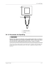
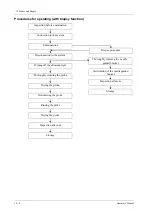
Page 227: ...guided biopsy procedure is performed Failure to do so may cause the probe and the needle guided bracket becomes a source of infection This section describes general procedures for operating the probe...

Page 228: ...em Examinations Wiping off the ultrasound gel Thoroughly cleaning the probe Drying the probe Disinfecting the probe Rinsing the probe Drying the probe Inspection after use Storage Biopsy procedure Ste...

Page 229: ...not be sufficient DO NOT use such a probe sheath The cover contains natural rubber latex and talc that can cause allergic reactions in some individuals DO NOT use an expired probe sheath Before using...

Page 230: ...First Street South Kalona IA 52247 9589 USA Tel 1 319 656 4447 E mail info civco com http www civco com Perform the following procedure to install the probe sheath 1 Place an appropriate amount of gel...

Page 231: ...use the probe to become deformed or damaged Observe the graph here carefully to immerse the probe Only soak parts of the probe below the strain relief Repeated disinfection will eventually damage the...

Page 232: ...ur hospital policy and procedures for cleaning Perform the following procedure 1 Wear a pair of gloves to prevent infection 2 Disconnect the probe from the system If the sheath is used take off the sh...

Page 233: ...r Observe the graph here carefully to perform disinfection Do not spray the strain relief on the connector end or the connector 4 Wipe away the residual disinfectant on the probe by using a piece of l...

Page 234: ...e residual disinfectant Repeat the operation twice Or follow the disinfectant manufacturer s instructions regarding rinsing 5 Dry the probe by wiping with a piece of clean disposable lint free soft cl...

Page 235: ...soft cloth Do not dry the probe by heating 4 Check whether the probe has defects such as peeling rifts bumps cracks or liquid spill If such defects exist the probe has reached the end of its service...

Page 236: ...erating 0 C 40 C 20 85 700 hPa 1060 hPa Storage and transportation 20 C 55 C 20 95 700 hPa 1060 hPa C11 3s Operating 0 C 40 C 30 85 700 hPa 1060 hPa Storage and transportation 20 C 55 C 30 95 700 hPa...

Page 237: ...a L20 5s Operating 0 C 35 C 15 80 700 hPa 1060 hPa Storage and transportation 20 C 60 C 15 90 500 hPa 1060 hPa 7LT4s Operating 0 C 40 C 25 90 550 hPa 1060 hPa Storage and transportation 20 C 60 C 10 9...

Page 238: ...biopsy needle may fail to penetrate the target The incorrect biopsy may cause various side effects in the patient Use a needle guided bracket other than that provided Mount the needle guided bracket...

Page 239: ...displayed on the ultrasound image does not indicate the actual position of the biopsy needle Therefore it should only be used as a reference Always monitor the relative positions of the biopsy needle...

Page 240: ...ed Brackets Available Some of the probes have matched needle guided brackets for biopsy the available probes and the corresponding needle guided brackets are listed as follows Probe Needle Ultrasound...

Page 241: ...16G 17G 18G L9 3s NGB 034 Metal needle detachable 40 50 60 14G 16G 18G 20G 22G C4 1s NGB 036 Metal needle detachable 7 25 35 14G 16G 18G 20G 22G L12 3RCs NGB 043 Metal needle detachable Angle range 3...

Page 242: ...needle guided bracket immediately stop using it and contact MINDRAY Customer Service Department or sales representative Sterilize the needle guided bracket before and after use Put on the sterile prob...

Page 243: ...en turn the retaining clamp to align it with the probe c When the retaining clamp is turned to the correct position the locking nut will lock the retaining clamp and the needle guided bracket is then...

Page 244: ...hand Match the groove and tab with the tab and groove of the probe respectively Mount the bracket onto the probe c Screw the pinch nut of the needle guided bracket to ensure that the needle guided bra...

Page 245: ...k and push it into the groove above the angle block then clamp it tightly b Screw the block s nut to secure the block c Insert a biopsy needle with the same specification as that of the guiding block...

Page 246: ...terile probe sheath b Hold the probe by one hand select the proper needle guided bracket and hold it with the other hand Align the narrow end tab of the needle guided bracket with the groove of the pr...

Page 247: ...e guiding block a Select a proper guiding block and push it into the groove above the angle block and clamp it tightly b Insert a biopsy needle with the same specification as that of the guiding block...

Page 248: ...NGB 010 Metal needle detachable needle guided bracket Perform the following procedure 1 Install the needle guided bracket a Put on the sterile probe sheath 1 Guiding block 2 Guiding hole of the biopsy...

Page 249: ...le guided bracket to match with the tabs of the probe Set the needle guided bracket at the desired position turn tightly the knob of fixing needle guided bracket to fix the needle guided bracket d Che...

Page 250: ...edle guided bracket a Put on the sterile probe sheath b Connect the locating groove on the clamp with the two raised edges on the probe head and align the locating pit of the clamp with the convex poi...

Page 251: ...ount the bracket onto the probe c Screw the pinch nut of the needle guided bracket to confirm that the needle guided bracket is properly installed on the probe 2 Adjust the needle angle to the proper...

Page 252: ...ck pin and close the V shaped cover to fix the lock pin in the groove of the needle type adjusting base so as to install the needle into the guiding hole 4 Release the needle from the bracket a Pull t...

Page 253: ...onto the probe c Screw the pinch nut of the needle guided bracket to ensure that the needle guided bracket is properly installed on the probe 2 Adjust the needle angle to the proper shift as required...

Page 254: ...o the guiding block hole 4 Release the needle from the bracket a Loosen the guiding block s nut and slightly move the guiding block in the direction of the needle s tail b Separate the residual part o...

Page 255: ...taining nut to fix the bracket and the probe 2 Adjust the needle angle to the proper shift as required a Loosen the angle pinch nut b Adjust the angle block to the desired level c Tighten the angle pi...

Page 256: ...nd the needle leans to V shaped block c Hold the probe and release the pressure position of the needle Adjust the needle type adjusting nut manually following the direction of the arrow The needle mov...

Page 257: ...from the needle 5 Remove the needle guided bracket a Rotate the clamping nuts of the needle guided bracket on right and left side following the direction of the arrow The needle guided bracket is sep...

Page 258: ...groove c Push the biopsy forward arrow s direction until the locating pole inserting into the location hole Turn the lower clamp against the intra cavity probe Tighten the nut to lock the biopsy arro...

Page 259: ...Metal needle detachable needle guided bracket Perform the following procedure 1 Install the needle guided bracket a Put on the sterile probe sheath 1 Needle fixing nut 2 Guiding groove 3 Angle fixing...

Page 260: ...ired level c Tighten the angle pinch nut 3 Insert the biopsy needle a Adjust the dial scale to the required needle type shift b Pull the lock pin and close the V shaped cover to fix the lock pin in th...

Page 261: ...s of the probe c Mount the bracket onto the probe and rotate the locking nut to fix the bracket 2 Insert the biopsy needle a Insert a biopsy needle into the guiding block hole b Adjust the biopsy angl...

Page 262: ...the probe b Hold the probe and take out the bracket NGB 044 Metal needle detachable needle guided bracket Perform the following procedure 1 Install the needle guided bracket 1 Right clamp 2 Groove 3...

Page 263: ...abs of the probe c Mount the bracket onto the probe and rotate the locking nut to fix the bracket 2 Adjust the needle angle to the proper shift as required a Loosen the depth pinch nut b Adjust the de...

Page 264: ...to the guiding block hole 4 Remove the needle guided bracket a Hold the probe and remove the needle b Loosen the guiding block nut and remove it from the guiding block fixing frame c Rotate the clampi...

Page 265: ...the needle guided bracket a Put on the sterile probe sheath b Align the needle guided bracket with the probe to align the locating bulges on the needle guide with the locating grooves on the probe th...

Page 266: ...he probe and insert the needle into Needle entry of the needle guide 2 Remove the needle guided bracket a Hold the probe and remove the needle b Hold the probe and raise the needle guided bracket to s...

Page 267: ...gle pinch nut 3 Insert the biopsy needle a Hold the probe Press the separation pressure position to separate needle guided V shaped block from pressure position of the needle b Put the needle into the...

Page 268: ...sy to enter Biopsy Select the biopsy bracket angle guide line If the needle guided bracket supports more than one biopsy angle select the angle guideline by using Biopsy Kit Select the guide line dot...

Page 269: ...ctual situation Tap Verify to enter Biopsy Verify menu to fine tune the guide line if needed 4 If available use iNeedle function to help enhance the needle visualization when the needle display is not...

Page 270: ...e g liquinox MetriZyme by using distilled or softened water in accordance with the operator s manual provided by the manufacturer 4 Detach all the detachable parts of the needle guided bracket and imm...

Page 271: ...guided bracket inside a high temperature steam sterilizer and perform sterilization The sterilization parameters are 121 C and 30 minutes for a gravity displacement steam sterilizer and are 132 C and...

Page 272: ...trackball trackpad to change the mark position and by adjusting lithotripsy machine tools or patient posture to locate the stone center at the mark b Read the depth of the mark by observing the depth...

Page 273: ...professional the eSpacial Navi system can achieve precision as high as 2 4 mm Place the magnetizer in the proper position to prevent the magnetizer from falling off or becoming damaged DO NOT make the...

Page 274: ...ype 5 Scale of guideline 5 mm scale 6 Projection position of the needle guidance trajectory in the ultrasound plane 7 Position at which the needle cross the ultrasound plane 8 Needle projection positi...

Page 275: ...eS Navi Needle menu Do not move the probe during the calibration 3 Magnetize a needle cap a Place an appropriate sterile needle cap length 3 5cm to 4 5cm diameter 7 mm with bottom closed into the mag...

Page 276: ...the maximum value the needle guidance information disappears temporally 2 Adjust the needle position and angle to define the position for inserting the needle Pay attention to the field strength durin...

Page 277: ...with a disinfectant Follow the disinfectant manufacturer s recommended contact time and mode Table 16 7 Compatible disinfectants Trade Name Manufacturer Chemical Name Procedures Surfa safe Anios Labor...

Page 278: ...of water about 2 gallons for at least 1 minute to remove all chemical residues on it Or follow the rinsing method recommended by the disinfectant manufacturer to rinse the magnetizer 4 Wipe off the wa...

Page 279: ...save the recording file automatically you can select to save in local disk U disk or optical disk Perform the following procedure 1 Perform ultrasound exams select appropriate views and adjust paramet...

Page 280: ...nding progress the icon displays as 17 3 DVR Video Replay You can replay the video and audio record 17 3 1 Replay on PC Connect the USB disk or optical disk with the file to the PC open the file direc...

Page 281: ...aintenance 18 1 1 Cleaning the System WARNING For the system equipped with trackball before cleaning the system be sure to turn off the power and disconnect the power cord from the outlet If you clean...

Page 282: ...to air dry Perform the following procedure 1 Use a soft dry cloth to wipe away dust attached to the inside outside and gaps in the probe holder Use a soft brush to brush away dust or stains from the...

Page 283: ...mall ball otherwise the small ball may drop down When liquid is spray onto the trackball area most of the liquid can be discharged through the waterspout besides you can dry the leaving water using th...

Page 284: ...controlling infection For the method to control infection consult your hospital s infection control officer or epidemiologist CAUTION Never immerse any part of the main unit in liquids or allow liquid...

Page 285: ...elect to lock the system for 10 seconds to disinfect the system while the power is On After cleaning disinfect the system as follows 1 Wear medical gloves to prevent infection 2 Disinfect the main uni...

Page 286: ...he connector pins are bent destroyed or falling off Content Description Color and B W video printer First wipe off dust or stain attached to the cover of printer with soft dry cloth then clean the ins...

Page 287: ...e power indicator of the monitor is lit up but the image is blank The interval between turning off and restarting the system is too short wait at least 20 seconds Turn off the system and wait at least...

Page 288: ...This page intentionally left blank...

Page 289: ...low power visible LED DO NOT stare into beam because of unknown hazards of transient radiation provided by class 2 laser DO NOT stare into beam emitted by SYMBOL DS4308 for more than 10 s CAUTION Ens...

Page 290: ...ector is properly secured 2 Connect the other end of the interface cable to the host A 1 2 Setting The reader has factory settings please refer to A 4 for details The reader supports some user defined...

Page 291: ...ameter Low Volume Medium Volume High Volume Code 93 and codebar scanning To enable or disable Code 93 scan the appropriate barcode below To enable Codebar scan the appropriate barcode below Code 39 fu...

Page 292: ...decode only I 2 of 5 symbols with 8 characters scan I 2 of 5 One Discrete Length then scan 0 followed by 8 A 1 3 Scanning in Hand Held Mode Perform the following procedure 1 Ensure all connections ar...

Page 293: ...y back into the reader from the barcode is known as specular reflection This specular reflection can make decoding difficult You can tilt the reader up to 55 forward or back and achieve a successful d...

Page 294: ...t provided Perform Scanning in Hands Free Mode When the reader is seated in the scanner cup the reader s built in sensor places the reader in hands free mode When you remove the reader from the stand...

Page 295: ...ple The 2 D barcode reader supports hand held operation mode Hand held mode press the trigger to decode A 2 1 Overview 1 LED Green A barcode was successfully decoded Red A data transmission error or r...

Page 296: ...t the other end of the interface cable to the host Removing the Interface Cable Perform the following procedure 1 Using the tip of a screwdriver or some other tools with a sharp head depress the cable...

Page 297: ...me Code 93 and codabar setting To enable Code 93 scan the appropriate barcode below To enable Codabar scan the appropriate barcode below Code 39 full ASCII setting Code 39 Full ASCII is a variant of C...

Page 298: ...ct the length using the numeric barcodes below For example to decode only I 2 of 5 symbols with 8 characters scan I 2 of 5 One Discrete Length then scan 0 followed by 8 A 2 4 Scanning in Hand Held Mod...

Page 299: ...gital imager reader beeps indicating the barcode is successfully decoded Steps 2 4 above may be required to repeat on poor quality or difficult barcodes The aiming pattern is smaller when the digital...

Page 300: ...ropriate interface cable to the barcode reader 3 Plug the other end of the cable into a free USB port on the Ultrasound system 4 Once the imager has been fully connected power on the Ultrasound System...

Page 301: ...is properly connected to the Ultrasound System before scanning After the barcode is successfully scanned the barcode reader buzzes and the green indicator is On Configuration before use Perform the f...

Page 302: ...Wipe the window using a tissue moistened with ammonia water Do not spray water or other cleaning liquids directly into the window A 5 Parameter Defaults Refer to the following table for parameter def...

Page 303: ...Disable UPC E1 Preamble System Character Code 128 Emulation Disable Convert UPC E to A Disable Data Matrix Enable Convert UPC E1 to A Disable Maxicode Enable EAN 8 JAN 8 Extend Disable QR Code Enable...

Page 304: ...This page intentionally left blank...

Page 305: ...result Be sure to connect the equipotential wire before inserting the power plug into the receptacle be sure to remove the power plug from the receptacle before disconnecting the equipotential wire o...

Page 306: ...t AC supply 7 Power outlet Supplies the power for peripheral devices 8 Power adapter bracket Used for placing the power adapter 9 Lifting column Used for adjusting the height of operation panel 10 Pro...

Page 307: ...nk purchased separately instead NOTE Keep the main unit tray carefully for future use after it is removed from the trolley Reinstall the main unit tray to the trolley if the U Bank has been removed fr...

Page 308: ...This page intentionally left blank...

Page 309: ...An electrical safety inspection should be periodically performed every two years The safety analyzer is also an excellent troubleshooting tool for detecting abnormalities in line voltage and groundin...

Page 310: ...Earth Leakage Test Run an Earth Leakage test on the device being tested before performing any other leakage tests The following outlet conditions apply when performing the Earth Leakage test normal p...

Page 311: ...ngle Fault Condition reverse polarity with open earth Single Fault Condition LIMITS For ES 60601 1 100 A in Normal Condition 300 A in Single Fault Condition For IEC 60601 1 100 A in Normal Condition 5...

Page 312: ...Polarity Reversed Polarity LIMITS For BF applied parts 5000 A C 9 Patient Auxiliary Current Patient Auxiliary currents are measured between any selected Applied Part connector and the remaining Applie...

Page 313: ...d excess the router capacity please refer to settings of the router generally it should be 5 DO NOT connect devices other than specified into the LAN Medical devices within the same LAN may interfere...

Page 314: ...or after successful connection 5 Click Refresh to refresh the Wireless Network Connection list D 2 IP Configure NOTE When the system background is processing network task DICOM sending for example ple...

Page 315: ...er If Static is selected using a static IP address enter the IP address IP address of the system should be in the same network segment with the server 2 Click OK to save current setting Click Cancel t...

Page 316: ...This page intentionally left blank...

Page 317: ...lable under abdominal gynecological urological obstetrical small parts and nerve block area E 1 Use iScanHelper for Reference Perform the following procedure 1 Perform ordinary scanning procedure 2 Pr...

Page 318: ...or Ultrasonic image to go to the single window of each of them Double click single window again to return to quad window display 1 Section selecting box Move the cursor onto the target view and press...

Page 319: ...mode 3 Select an item in the list and click Start to begin the demonstration 4 Click Exit to exit iVision status F 1 Demonstration item Demonstration items are image files in formats supported by the...

Page 320: ...delete selected files or catalogs from the file list Clear to clear all the files or catalogs in the file list Export to export selected directories files to external storage devices Click Export to b...

Page 321: ...n off Power Mode M Mode Turn on off M Mode PW Mode Turn on off PW Mode 3D Turn on off 3D Mode Freeze Freeze Image UnFreeze UnFreeze Image Clear Clear Dual Enter Dual Windows Format Quad Enter Quad Win...

Page 322: ...Switch Exam Mode to Abdomen Vascular Neonatal Abdomen Switch Exam Mode to Neonatal Abdomen Adult Cardiac Switch Exam Mode to Adult Cardiac Cardiac Difficult Switch Exam Mode to Adult Cardiac Difficult...

Page 323: ...to Emergency Obstetrics Emergency Vascular Switch Exam Mode to Emergency Vascular Emergency Superficial Switch Exam Mode to Emergency Superficial Lung Switch Exam Mode to Lung Neonatal Head Switch Exa...

Page 324: ...of Vocal Commands Close Report Dialog Close Report Dialog Open Preset Dialog Open Preset Dialog Close Preset Dialog Close Preset Dialog Smart IVC Smart IVC Smart VTI Smart VTI Smart B lines Smart B l...

Page 325: ...nostic ultrasound instruments the possibility exists that such biological effects may be identified in the future Thus ultrasound should be used in a prudent manner to provide medical benefit to the p...

Page 326: ...s MI is an index that shows the possibility of the cavitations generation based on acoustic pressure and the value in which the peak rarefactional acoustic pressure is divided by the square root of th...

Page 327: ...coustic power percentage the greater the current acoustic output When the image is frozen the system stops transmitting acoustic power Default setting of acoustic power Selection of diagnostic applica...

Page 328: ...overall depth and PRF The operating mode determines whether the ultrasound beam is scanning or non scanning Thermal bioeffect is closely connected to M mode Doppler and Color mode Acoustic attenuation...

Page 329: ...setting of the system increases or decreases the possibility of Thermal or Mechanical effect More specifically they were designed to assist in the implementation of the ALARA principle As an operator...

Page 330: ...ipment Part 2 37 Particular requirements for the basic safety and essential performance of ultrasonic medical diagnostic and monitoring equipment issued by IEC in 2015 IEC 62359 Ultrasonics Field char...

Page 331: ...should be avoided because it could result in improper operation If such use is necessary this equipment and the other equipment should be observed to verify that they are operating normally Use of ac...

Page 332: ...in such an environment EMISSIONS TEST COMPLIANCE ELECTROMAGNETIC ENVIROMENT GUIDANCE RF emissions CISPR 11 Group 1 The system uses RF energy only for its internal function Therefore its RF emissions...

Page 333: ...E AND MINDRAY DECLARATION ELECTROMAGNETIC IMMUNITY The system is intended for use in the electromagnetic environment specified below The customer or the user of system should assure that it is used in...

Page 334: ...ains interruptions it is recommended that our product be powered from an uninterruptible power supply or a battery Power frequency 50 60 HZ magnetic field IEC 61000 4 8 30 A m 30 A m Power frequency m...

Page 335: ...ould be less than the compliance level in each frequency range Interference may occur in the vicinity of equipment marked with the following symbol Radiated RF IEC 61000 4 3 10 V m 80MHz 2 7GHz 10 V m...

Page 336: ...ers at a maximum output power not listed above the recommended separation distanced in meters m can be determined using the equation applicable to the frequency of the transmitter where P is the maxim...

Page 337: ......

Page 338: ...P N 046 018835 00 2 0...

Reviews: