Understanding the System Principles
3-8
3.5 RBC/PLT Measurement
3.5.1 Volumetric Metering
An accurate cell count cannot be obtained unless the precise volume of diluted sample that
passes through the aperture during the count cycle is known. This analyzer uses a volumetric
metering unit to control the count cycle and to ensure that a precise volume of sample is
analyzed for the measurement.
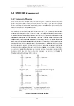
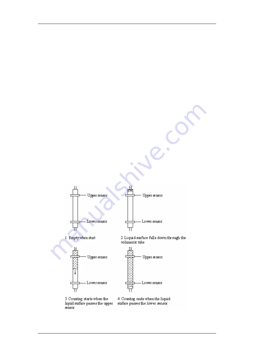
The metering unit controlling the RBC/PLT count cycle consists of a metering tube with two
optical sensors mounted on it, as Figure 3-3 shows. This tube ensures that a precise amount
of diluted sample is measured during each count cycle. The exact amount is determined by
the distance between the two optical sensors. The rinse is used to create a meniscus in the
metering tube. The count cycle starts when the meniscus reaches the upper sensor and
stops when the meniscus reaches the lower sensor. The amount of time required for the
meniscus to travel from the upper sensor to the lower sensor is called the RBC Count Time
and is measured in seconds. At the end of the count cycle, the measured count time is
compared to the pre-defined reference count time (see
Chapter 5.3
for details). If the former
is less than or greater than the latter by 2 seconds or more, the analyzer will report RBC
bubbles or RBC clog error. Seeing the error message, refer to
Chapter 11 Troubleshooting
Your Analyzer
for solutions.
Figure 3-3 Volumetric metering process
Summary of Contents for BC-2800
Page 1: ...BC 2800 Auto Hematology Analyzer Operator s Manual ...
Page 2: ......
Page 12: ......
Page 24: ...Using This Manual 1 12 Figure 1 4 High voltage warning label 7 High Voltage 7 ...
Page 62: ......
Page 91: ...Customizing the Analyzer Software 5 29 Figure 5 46 Saving changes ...
Page 92: ......
Page 170: ...Using the QC Programs 8 14 Figure 8 18 Transmission dialog box ...
Page 196: ......
Page 248: ......
Page 252: ......
Page 266: ......
Page 284: ...Appendices E 10 Hemoglobin Concentration ...
Page 286: ...P N 2800 20 28795 2 0 ...


