5-29
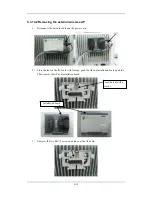
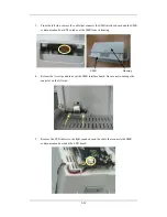
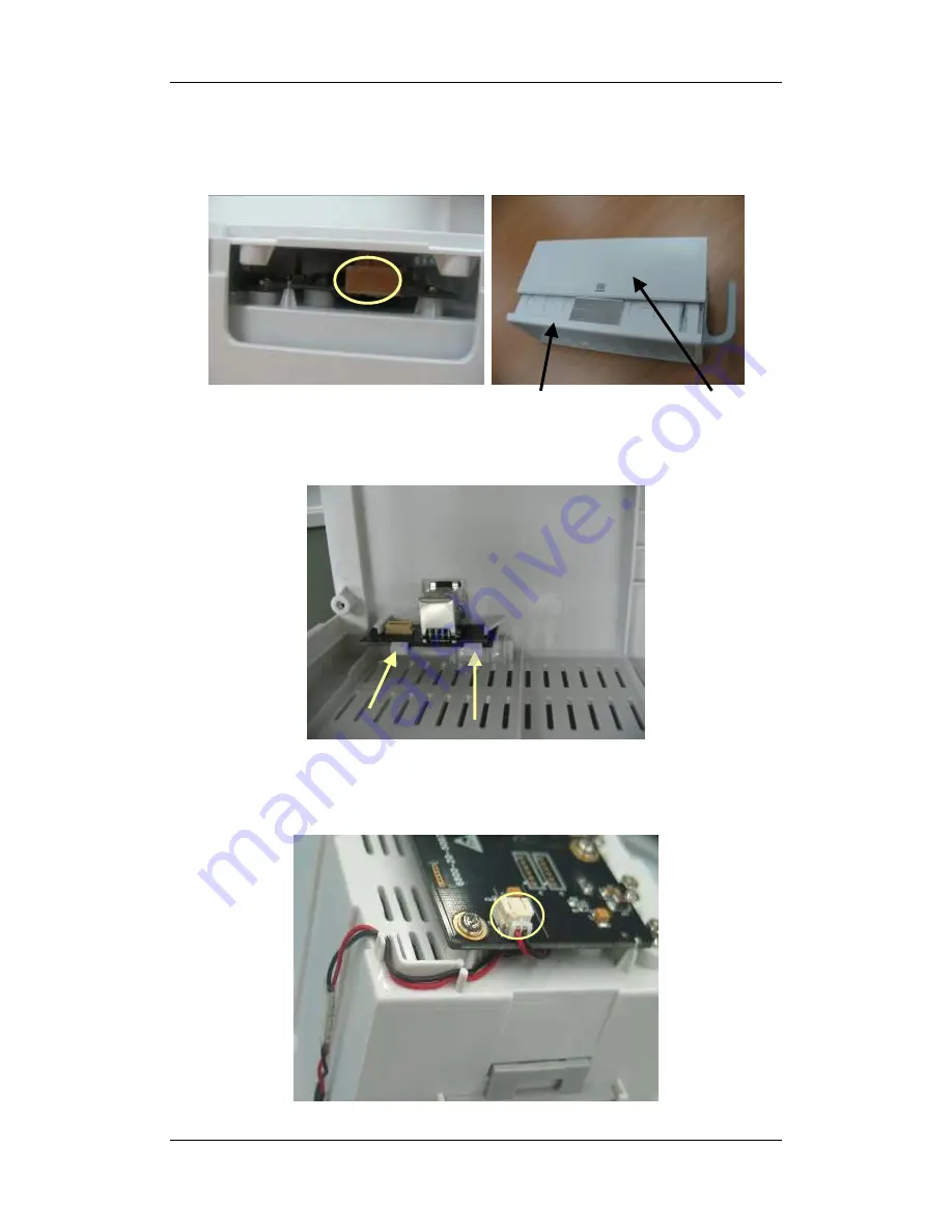
3. From the left side, remove the cable that connects the SMR interface board and the SMR
communication board. Then take out the SMR from its housing.
4. Release the two clips and take out the SMR interface board. Be sure not to damage the
snap slot on the left side.
5. Remove the LED indicator, the light conductor and the cable that connects the SMR
communication board and the LED board.
Housing
SMR
Summary of Contents for BeneView T5
Page 1: ...DPM 6 Patient Monitor Service Manual ...
Page 2: ......
Page 4: ...II FOR YOUR NOTES ...
Page 12: ...6 FOR YOUR NOTES ...
Page 16: ...1 4 FOR YOUR NOTES ...
Page 32: ...2 16 FOR YOUR NOTES ...
Page 68: ...3 36 FOR YOUR NOTES ...
Page 80: ...4 12 FOR YOUR NOTES ...
Page 126: ...5 46 FOR YOUR NOTES ...
Page 133: ...6 7 6 3 3 12 1 Screen Assembly with anti glare screen Exploded View ...
Page 163: ...6 37 6 6 7 BIS Module Exploded View ...
Page 180: ...6 54 FOR YOUR NOTES ...
Page 204: ...A 14 FOR YOUR NOTES ...
Page 205: ......


