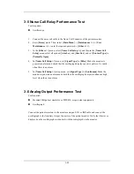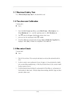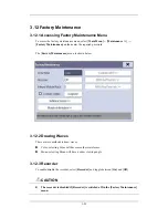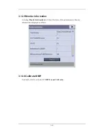
3-19
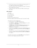
5. Adjust the calibration value in the [
Maintain IBP
] menu until it is equal to the reading
of sphygmomanometer
6. Select
the
[
Calibrate
] button to start a calibration
7. The
message
[
Calibration Completed!
] is displayed after a successful calibration. If
the calibration failed, the prompt [
Calibration Failed!
] will be displayed.
3.4.7 C.O. Test
Tools required:
Medsim300B Patient simulator, or MPS450, or equivalent equipment
C.O. adapter box (CI-3 module/cable, P/N: 3010-0289 for 300B, P/N: 5180500 for
MPS450)
C.O. trunk cable (PN: 0010-21-42716)
Follow this procedure to perform the test:
1. Connect the patient simulator and the C.O. module using a C.O. trunk cable and a C.O.
adapter box.
2. Set the blood temperature (BT) to 37ºC on the patient simulator and check the
temperature value displayed on the monitor is 37 ± 0.2ºC.
3. On the patient monitor, set [
Auto IT
] to [
Off
], [
IT
] to 2ºC, and [
Comp. Const.
] to
0.595 in the [
C.O. Setup
] menu. Select [
C.O. Measure
] to enter the C.O. measurement
window.
4. Select
[
Start
] in the C.O. measurement window to start C.O. measurements.
5. On the patient simulator, set C.O. to 5L/min and wait for 3 to 10 seconds.
6. Verify that the C.O. value displayed on the monitor is 5±0.25L/min.
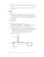
Sphygmomanometer
T-shape connector
3-way stopcock
Pressure transducer
Pressure adapter cable
IBP Module
Summary of Contents for BeneView T5
Page 1: ...DPM 6 Patient Monitor Service Manual ...
Page 2: ......
Page 4: ...II FOR YOUR NOTES ...
Page 12: ...6 FOR YOUR NOTES ...
Page 16: ...1 4 FOR YOUR NOTES ...
Page 32: ...2 16 FOR YOUR NOTES ...
Page 68: ...3 36 FOR YOUR NOTES ...
Page 80: ...4 12 FOR YOUR NOTES ...
Page 126: ...5 46 FOR YOUR NOTES ...
Page 133: ...6 7 6 3 3 12 1 Screen Assembly with anti glare screen Exploded View ...
Page 163: ...6 37 6 6 7 BIS Module Exploded View ...
Page 180: ...6 54 FOR YOUR NOTES ...
Page 204: ...A 14 FOR YOUR NOTES ...
Page 205: ......


