Principle Description
3-2
3.2
Principle of Boards
3.2.1 Transducer Board
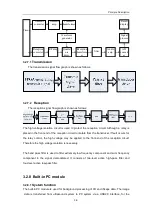
The block diagram of the transducer board is shown as follows:
Rela
y-EN0
Re
lay-EN2
Rela
y-EN1
Rela
y-EN3
The transducer board is designed for switching between the transducers and recognition of
the transducer IDs. The transducer switching signal controls the relays to switch between
the transducers, and the ID reading circuit is independent of the transducer switching circuit
and can read out the IDs of the transducers.
For A, B, C, and D transducers, the channel, double-pole double-throw relays are respectively
adopted to control the status of the transducer. Now take relay drive of the transducer A as an
example to describe the principle of the transducer switching. After the transducer select
control signal D_Relay-ENA is driven by 245, the four-channel signal D_Relay-ENA is
obtained. The four-channel signals are respectively driven by four relays to generate the
eight-channel signals A The A signals respectively control channel relays, so that the element
of the transducer A can be selected.
The transducer ID codes are selected by the signal CS and read into CPLD. After the system
reads out a transducer’s ID code, the system software will set the D_Relay-ENX (X
Summary of Contents for DC-6
Page 1: ...DC 6 DC 6T DC 6Vet Diagnostic Ultrasound System Service Manual...
Page 2: ......
Page 20: ...2 1 2 System Overview 2 1 System Appearance 2 1 1 Complete System with CRT Monitor...
Page 23: ...System Overview 2 4 2 2 LCD Monitor...
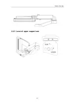
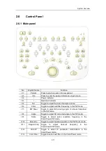
Page 26: ...System Overview 2 7 2 2 3 Lever of upper support arm...
Page 66: ...4 1 4 System Structure and Assembly Disassembly 4 1 Exploded View of Complete System...
Page 101: ...System Structure and Assembly Disassembly 4 36 Power boards Card detacher...
Page 191: ...P N 2105 20 40473 V10 0...

