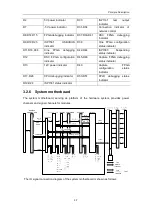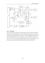
Principle Description
3-9
Transmit
converter
Transmit
beamformer
Transmit
amp
Waveform
generator
Reception
converter
RF amp
Reception
beamform
er
Quadrat
ure
demo
filter
Audio
amp
Tissue
AD
convert
er
Signal
process
Result
display
3.2.7.1
Transmission
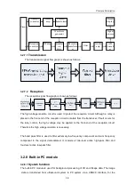
The transmission signal flow graph is shown as follows:
3.2.7.2
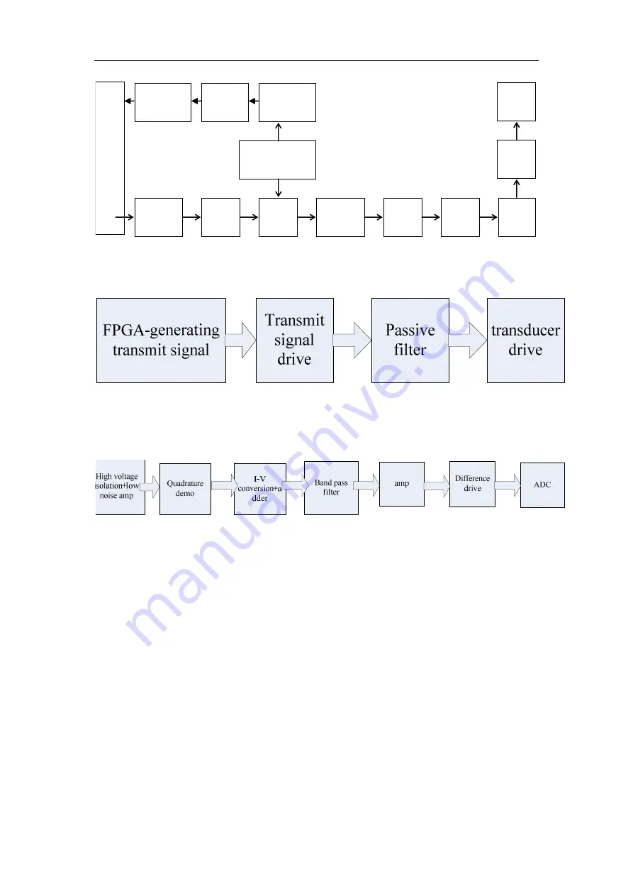
Reception
The reception signal flow graph is shown as follows:
The high voltage isolation circuit is used to protect the reception circuit. Although a relay is
placed in the front-end of the reception circuit to isolate from the transducer, if fault occurs for
the relay control, the high voltage may be applied to the front-end of the reception circuit.
Therefore the high voltage isolation is necessary.
The band pass filter is used to filter extremely low frequency component and sum frequency
component in the signal demodulated. It consists of two-level active high-pass filter and
four-level active low-pass filter.
3.2.8 Built-in PC module
3.2.8.1
System function
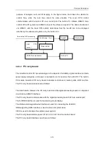
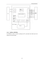
The built-in PC module is used for background processing of 3D and iScape data. The image
data is transferred from ultrasound system to PC system via a USB2.0 interface, for the
Summary of Contents for DC-6
Page 1: ...DC 6 DC 6T DC 6Vet Diagnostic Ultrasound System Service Manual...
Page 2: ......
Page 20: ...2 1 2 System Overview 2 1 System Appearance 2 1 1 Complete System with CRT Monitor...
Page 23: ...System Overview 2 4 2 2 LCD Monitor...
Page 26: ...System Overview 2 7 2 2 3 Lever of upper support arm...
Page 66: ...4 1 4 System Structure and Assembly Disassembly 4 1 Exploded View of Complete System...
Page 101: ...System Structure and Assembly Disassembly 4 36 Power boards Card detacher...
Page 191: ...P N 2105 20 40473 V10 0...

