(
2
)
Structure and Assembly/Disassembly of the Machine
18 power socket
2302-21-29147
1
19 power switch
2100-10-07943
1
20 main board connector
2302-20-29208
1
21 digital board
2302-30-34403
1
22 main board support
2302-20-29110
1
23 shield spring
2302-20-29245
2
24 transducer board shield cover
2302-20-29198
1
25 transducer board
2302-30-34407
1
26 transducer socket fixed plate
2302-20-29101
1
27 shield spring A
2102-20-16918
4
28 shield spring B
2102-20-17113
4
29 transducer socket fastener
2302-20-29199
2
1.4Disassembly
1.4.1Disassembly of the rear cover
1.
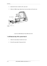
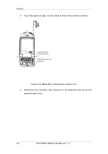
Remove the transducer cable hook
Figure 2-8 Disassembly of the rear cover
Turn the transducer cable hook clockwise to the end;
Take out the transducer cable hook upward.
2.
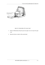
Remove the handle and the winding rack
DP-3300/DP-3200
Service Manual
(
V1.1
)
2-7
(
1
)
Summary of Contents for DP-3200
Page 1: ...DP 3300 DP 3200 Digital Ultrasonic Diagnostic Imaging System Service Manual...
Page 2: ......
Page 11: ...DP 3300 DP 3200 Service Manual V1 1 I...
Page 12: ......
Page 16: ......
Page 20: ......
Page 76: ......
Page 81: ...P N 2302 20 34499 V 1 1...


