5-18 Image Optimization
5.7.1
Basic Procedures for Power Mode Imaging
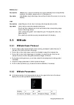
1. Select a high-quality image during B + Color scanning, and adjust to place the area of
interest in the center of the image.
2. Click [Power] on image menu to enter B + Power mode. Roll the trackball to change
position of the Region of Interest (ROI) and press the <Set> key to set. Roll the trackball
to change the size and position of ROI.
3. Adjust the image parameters during B + Power mode scanning to obtain optimized
image.
4. Perform other operations (e.g. measurement and calculation) if necessary.
5.7.2
Power Mode Image Parameters
In Power mode scanning, the image parameter area in the upper right corner of the
screen displays the real-time parameter values as follows:
Parameter F
G
PRF
WF
Meaning
Frequency Power Gain
Pulse Repetition
Frequency (PRF)
Power Wall Filter
In Power mode, acoustic power is synchronous with that of B mode. Adjustment of the
depth to the B mode image will lead to corresponding changes in Power mode image.
Parameters consistent with those in Color mode and B mode are not to be introduced,
please refer to relevant sections of the Color mode and B mode, while special items of the
Power mode are introduced in the following.
5.7.3
Power Mode Image Optimization
Power Gain
Description
Refers to the overall sensitivity to flow signals, and this function is used to
adjust the gain in Power mode.
The real-time gain value is displayed in the image parameter area in the upper
right corner of the screen.
Operations
Rotate the <Gain/iTouch> knob to adjust the gain.
The adjusting range is 0-100.
Effects
Increasing the gain will increase the flow signal presented as well as noise,
while the signals may be missing when the gain is adjusted too low.
Power Map
Description
This feature indicates the display effect of Power image.
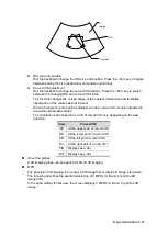
The maps in the Power mode image are grouped into two categories: Power
maps and Directional Power maps.
Summary of Contents for DP-50 Exp Vet
Page 2: ......
Page 34: ...2 6 System Overview 2 6 Introduction of Each Unit Right View Left View...
Page 42: ......
Page 68: ......
Page 128: ......
Page 148: ......
Page 166: ...10 18 DICOM For details on tast manager see 9 6 Animal Task Manager...
Page 180: ......
Page 220: ......
Page 224: ......
Page 236: ......
Page 242: ......
Page 248: ......
Page 342: ...D 2 Printer Adapter Type Model SONY X898MD...
Page 343: ...P N 046 017713 02 1 0...


