background image

  11  Patient Data Management

Operator’s Manual

11 - 3

During image scan, saved image thumbnails will display on the right of the screen. Move the 
cursor onto a thumbnail, and tap twice to open the image; if the stored image is a cine file, 
double-click the thumbnail to enter the auto cine review.

To enter image review:

Tap [Review] to enter review page. Images of the current exam and the current patient are 
displayed.

Select an exam of a patient in the iStation screen, and click [Review] or double-click the 
exam to enter the Review screen to review the images of the patient.

Image Analysis

In image analysis status, you can view, zoom, perform image parameter adjustment and 
measurements, add comments and perform cine review for a stored image (FRM or CIN format).. 
The operation steps are the same as those for real-time scanning. See the relevant sections for 
details.

1.

To enter image analysis:

In the image scanning or freeze status, double-click a thumbnail stored in this exam to 
enter the image analysis status; or

In the image review status, double-click the selected thumbnail to open the image.

You can perform cine review operations in image analysis status.

2.

To exit the image analysis:

Tap [Freeze] to exit and enter the real-time scan status.

Tap [Return] to exit from the image analysis to the Review status.In image analysis status, 
the selected image is displayed on the screen, and the thumbnails of the same exam are 
displayed on the thumbnail area, you can turn pages using the buttons on the right side of 
the thumbnail.

11.1.6 Sending Image Files

NOTE:

Data saved this way can only be reviewed on the PC and cannot be restored to the ultrasound 
system. 

Perform the following procedure:

1.

Do one of the following to bring up the “Send To” screen:

In the iStation screen, select a stored image thumbnail and tap [Send To].

In the Review screen, select a image and tap [Send To].

2.

Select the desired destination.

NOTE:

If MedTouch is set as the desination, the file sent to MedTouch is transferred into PNG 
format, and the cine file is transferred into AVI format.

11.2

Report Management

11.2.1 Report storage

The exam reports are stored under the directory of the exam of the patient.

Summary of Contents for TE X

Page 1: ...TEX20 TEX20 Pro TEX20S TEX20T TEX20 Exp TEX20 Elite TEX10 TEX10 Pro TEX10S TEX10T TEX10 Exp TEX10 Elite TE X TE X Lite Diagnostic Ultrasound System Operator s Manual Basic Volume...

Page 2: ......

Page 3: ...used only for informational or editorial purposes They are the property of their respective owners This posting serves as notice under 35 U S C 287 a for Mindray patents http www mindrayna com patent...

Page 4: ...or damage caused by force majeure such as fire and earthquake Malfunction or damage caused by improper operation or repair by unqualified or unauthorized service people Malfunction of the instrument o...

Page 5: ...tor error or accidents This manual contains warnings regarding foreseeable potential dangers but you shall also be continuously alert to dangers other than those indicated Mindray shall not be liable...

Page 6: ...nding on the software version preset settings and optional configuration the actual interfaces may be different from those in this manual Conventions In this manual the following conventions are used...

Page 7: ...d Use 2 1 2 2 Contraindication 2 1 2 3 Safety Classifications 2 1 2 4 Product Specifications 2 2 2 4 1 Power supply 2 2 2 4 2 Environmental Conditions 2 2 2 4 3 Dimensions and Weight 2 2 2 5 Product D...

Page 8: ...2 15 1 Live capture 2 27 2 15 2 Freeze storage setting 2 27 2 16 Symbols and Warning Labels 2 27 3 System Preparation 3 1 3 1 Move Position the System 3 1 3 2 Connecting the Power Cord 3 1 3 2 1 Conne...

Page 9: ...4 4 Comment Preset 4 26 4 4 1 Comment Configure 4 27 4 4 2 Comment Group Define 4 27 4 5 iWorks Preset 4 28 4 5 1 Protocol Management 4 28 4 5 2 View Management 4 28 4 5 3 Create a New Protocol 4 28...

Page 10: ...6 13 6 8 TDI 6 15 6 8 1 TDI Mode Image Scanning 6 15 6 8 2 TDI Mode Image Parameters 6 15 6 8 3 TDI Quantitative Analysis 6 16 6 9 iScape View Real time Panoramic Imaging 6 19 6 9 1 Basic Procedures f...

Page 11: ...7 1 7 2 Image Parameters 7 1 7 3 Mass Measurement 7 2 8 Smart 3D 8 1 8 1 Overview 8 1 8 1 1 Terms 8 1 8 1 2 ROI and VOI 8 2 8 1 3 Render Mode 8 2 8 1 4 MPR 8 3 8 2 Note before Use 8 4 8 3 Smart 3D Ima...

Page 12: ...mage Printing 11 6 11 6 2 Report Printing 11 7 11 7 Patient Task Management 11 7 11 8 V Access 11 8 11 9 Q Path 11 8 11 10 X Link 11 9 12 DICOM HL7 12 1 12 1 DICOM Storage 12 1 12 1 1 Send images on i...

Page 13: ...nd Transportation 13 55 13 2 7 Disposal 13 56 13 3 Middle Line 13 56 13 4 eSpacial Navi 13 56 13 4 1 Interface 13 57 13 4 2 Preset 13 59 13 4 3 Preparation Before Needle Guidance 13 59 13 4 4 Procedur...

Page 14: ...E 3 Device Labeling E 2 E 4 Protective Earth Resistance E 2 E 5 Earth Leakage Test E 2 E 6 Enclosure Leakage Test E 3 E 7 Patient Leakage Current E 3 E 8 Mains on Applied Part Leakage E 4 E 9 Patient...

Page 15: ...Contents Operator s Manual ix I Indications for use I 1...

Page 16: ......

Page 17: ...se the leakage current to exceed the safety requirement In the environment that patient is 1 5 meters around connect peripherals to the auxiliary power outlet or power the peripherals by auxiliary out...

Page 18: ...the patient at the same time Do not use an aftermarket probe other than those specified by Mindray The probes may damage the system causing a profound failure e g a fire in the worst case Do not subje...

Page 19: ...his operator s manual does not describe clinical examination techniques The clinician should select the proper examination techniques based on specialized training and clinical experience Malfunctions...

Page 20: ...d in this manual Do not use gel disinfectant probes probe sheath or needle guided brackets that are not compatible with the system The applied contrast agency should be compliant with the relevant loc...

Page 21: ...or distortion and abrasion the image sensitivity and precision may become worse too To ensure optimal system operations it is recommended that you maintain the system under a Mindray service agreement...

Page 22: ...sinfected or sterilized Sterilization or high level disinfect before use is required Disposable components should be packaged sterile and for single use only Do not use if integrity of packaging viola...

Page 23: ...heaths pricing samples and local distribution For CIVCO information please contact the following CIVCO Medical Instruments Tel 1 800 445 6741 www civco com WARNING Allergic reactions in patients sensi...

Page 24: ...This page intentionally left blank...

Page 25: ...ntrast imaging Contrast agent for Liver 2 2 Contraindication None 2 3 Safety Classifications According to the type of protection against electric shock External powered class I equipment internally po...

Page 26: ...nditions Ambient temperature 0 C 40 C Relative humidity 20 85 no condensation Atmospheric pressure 700 hPa 1060 hPa Storage and transportation conditions Ambient temperature 20 C 55 C Relative humidit...

Page 27: ...reless network card built in GPU Accessories Operator s manuals Manual NEMA Ultrasound gel Probe holder Front storage bin 2 6 2 Probes and Needle guided Brackets Available Please refer to the Probes a...

Page 28: ...achable C11 3s NGB 022 Metal needle detachable SC6 1s C5 1s NGB 024 Metal needle detachable C6 2Gs NGB 025 Metal needle detachable V11 3Hs NGB 034 Metal needle detachable L9 3s NGB 036 Metal needle de...

Page 29: ...ured with eSpacial Navi 13 Foot switch Types 2 pedal 3 pedal 14 iVocal microphone iVocal Plus should be configured 15 iVocal Plus Microphone Array iVocal Plus should be configured 16 CW 17 Free Xros M...

Page 30: ...uding verify SCU and SCP task management DICOM Storage DICOM Print DICOM Storage Commitment DICOM Media Storage including DICOM DIR 44 DICOM Worklist DICOM Basic should be configured 45 DICOM MPPS 46...

Page 31: ...corresponding disposable needle guided brackets are listed as follows NOTE The disposable needle guided brackets are not configured or sold by Mindray The user can purchase them based on the specific...

Page 32: ...ct Dial 319 248 6757 International Fax 319 248 6660 E mail order civco com Internet www civco com 2 8 Introduction of Each Unit Figure 2 1 Overview of main unit No Name Function 1 Probe holder Used fo...

Page 33: ...ipment 6 Caster Used to fix or move the device 7 AC power cord Retractable AC power cord 8 Air Charge Module Configured with the air station to charge the main unit 9 Battery pack Supply power without...

Page 34: ...or connecting to ECG of the system 3 USB port Type A Used for connecting storage device such as USB disk bar code reader printer footswitch DVD recorder etc 4 HDMI High definition multimedia interface...

Page 35: ...nks in white 0 20 the L1 indicator blinks in white When the battery is in discharge the battery capacity indicators are as follows 80 100 the L1 L5 indicators and the battery symbol borders are all in...

Page 36: ...0 the L1 indicator blinks 4 Battery pack status indicator Indicates the battery charge and discharge status In charge When the capacity is 95 the indicator is in orange When the capacity is 95 the ind...

Page 37: ...stem NOTE Ensure the system is powered off before connecting the ECG module 2 ECG lead port Used for ECG signal input No Name Description 1 AC indicator Turns on in white color when connecting the Air...

Page 38: ...rator s Manual 2 System Overview 2 11 Basic Operations 2 11 1 Screen Display Figure 2 7 Landscape orientation of the monitor 1 17 2 3 4 5 6 7 8 9 10 11 13 14 15 16 12 1 17 2 3 4 5 6 7 8 9 10 11 13 14...

Page 39: ...he active window If there are more than one imaging modes the parameters are displayed by each mode 3 Acoustic output index Displays the acoustic power mechanical index and thermal index 4 Patient inf...

Page 40: ...tatus 13 Image mode area Displays the current modes Select and slide left or right to enter the corresponding mode 14 Switching key Select to change the currently active window Start stop image acquis...

Page 41: ...e connection range is within 3 meters Perform the following procedure 1 Connect suitable probes to the system and Select Probe button The screen displays the Probe and Exam dialog box 2 Select the pro...

Page 42: ...ain probe Create a new exam mode using current image settings user defined exam mode Perform the following procedure 1 2 3 No Name Function 1 Imaging mode area Select imaging buttons to switch tab 2 I...

Page 43: ...gs Perform the following procedure 1 Select QSave in the Menu area to bring out the Quick Save dialogue box 2 Select Restore to restore the probe and exam mode to factory settings View image parameter...

Page 44: ...lus to activate the function Inputting vocal command Perform the following procedure 1 Select the icon in the Audio Control menu to start the vocal command recognition No Name Function 1 Edit Comments...

Page 45: ...k spaces are not supported and a maximum of 30 characters are allowed when entering the Chinese characters the user defined commands cannot be empty User defined commands that are already exited in th...

Page 46: ...icon 3 Select B or select Dual to be Off to exit to single window 2 11 9 Image Magnification NOTE Zooming an image changes the frame rate which tends to change thermal indices The position of the foca...

Page 47: ...eview After selecting Freeze the system allows you to review and edit the images prior to the image being frozen This function is called cine review You can perform zoom measurements add comments and...

Page 48: ...the earlier stored images drag the playback mark to the right to display the recently stored images Select Minus Plus button to fine tune the playback mark Or swipe the image area to the right to dis...

Page 49: ...me synchronization mark on the time mark of M PW image indicates the corresponding 2D image and M PW image In statuses other than dual live status you can only review images in the currently active wi...

Page 50: ...comparison mode 2 Review the images of different image windows cine replaying can t be performed for single frame image file select Update or Dual to switch the active image window 3 Save the image i...

Page 51: ...of the image It also refers to saving the cine or cycles retrospectively With the ECG disabled Select Cine tab and use Time Retro to adjust it With the ECG enabled Select Cine tab Select Saving type R...

Page 52: ...this system are type BF applied parts The ECG leads within this system is type BF applied part Caution Standby Transducer sockets AC Alternating current Foot switch USB port Extending port High defin...

Page 53: ...sign Mind your head Warning Crushing of hands Equipotentiality Product serial number Manufacture date Manufacturer Temperature limit Humidity limitation Atmospheric pressure limitation Federal law res...

Page 54: ...ystem on a sloped surface Otherwise the system may slide resulting in personal injury or the system malfunction Two persons are required to move the system over a sloped surface 2 DO NOT sit on the sy...

Page 55: ...his system can work normally only when it is connected to the external power supply or the battery capacity is sufficient 3 2 1 Connecting Power 1 Connect the connector of the power adapter to the ada...

Page 56: ...area When the center lines on both sides of the Air Charging Module and the Air Station are aligned the distance between the Air Charging Module and the Air Station is within 10 mm and the center line...

Page 57: ...e to be close to the Air Station When the device is close to the Air Station the indicators at the both sides of the top of the Air Station will turn on and alarm sound will occur if there is deviatio...

Page 58: ...em is powered on The temperature relative humidity and atmospheric pressure meet the requirements of the operating conditions For details about the operating conditions see the System Overview chapter...

Page 59: ...d confirm the new password in the dialog box 4 Select Confirm to exit To lock the system Select in the top right corner of the screen and select Screen Lock to lock the system for 10 seconds 3 3 3 Che...

Page 60: ...power off without displaying the Shutdown Confirm screen However shutting down the system this way may destroy the data DO NOT rush direct shutdown of the system It may damage the data After the syste...

Page 61: ...control NOTE Avoid operating in direct sunlight or the touch screen could be obscured 3 5 Display Position Adjustment Gently hold the bottom edge of the display when adjusting its position The displa...

Page 62: ...the proper position to prevent the probe from falling off or becoming damaged Only use probes provided by Mindray Aftermarket probes may result in damage or cause a fire 3 6 1 Connecting a Probe WARNI...

Page 63: ...in fully 2 Toggle the locking lever to the left position 3 Position the probe properly to avoid it being treaded on or becoming wrapped around other devices DO NOT allow the probe head to hang free 3...

Page 64: ...connecting and then connecting again several times or try another USB disk If the problem still exists please contact Mindray service engineer 3 8 Connecting the Footswitch The system supports USB por...

Page 65: ...the following procedure 1 Place the printer appropriately 2 Connect the power cord of the printer to a receptacle Connect the USB port of the system to the USB port of the printer with USB cable 3 Lo...

Page 66: ...the ultrasound machine and the printer are connected to a same LAN and turned on the W LAN function of the printer 4 Select in the top right corner of the screen and select Setup System Peripheral Pri...

Page 67: ...ter settings are saved Select Cancel in the Setup menu to close the Setup menu If you change the system language and tap Save in the Setup menu the system automatically shuts down to make the modifica...

Page 68: ...or decrease the required value by clicking the icons on the right side Time Synch To assign a time server and make the time of the ultrasound machine consistent with the server Item Description Type...

Page 69: ...l be deleted and unrecoverable it is recommended to perform patient data backup before enabling this function to avoid data loss Remind exams backup after To set number of days to remind the operator...

Page 70: ...e time of picture position changing interval iZoom For 21 5 inch screen iZoom when powering on the system To set enter the iZoom mode automatically when startup Enable iZoom Select whether to enable i...

Page 71: ...n the function that when moving PW CW sampling line B image is activated under B Color PW CW mode Full Image Linear After it is ticked if a linear probe is used and the depth value is low the image wi...

Page 72: ...easurements Cursor Size The size of the cursor Heart Beat The number of cardiac cycles in the heart rate calculation In heart rate measurement the number of cardiac cycles should match the preset numb...

Page 73: ...set the fetal weight display Perform the following procedure 1 Enter the Fetal Calc page 2 Select the Fetal Weight Unit Select Metric English or English Metric from the drop down list 3 Select the fo...

Page 74: ...Maximum value enter the number of days without the unit GA table NOTE Fill in the table according to the actual clinical values except for those cells with bold text FG The author name Value of stand...

Page 75: ...the left column and the system asks if to add a formula 4 Click OK to select the csv file formula file for the item Or add a formula for the new item by clicking Import Measure Result EDD display the...

Page 76: ...ion images and reports etc Enabling Access Control The system administrator can preset the access controls that is whether an operator has the right to access data in the system Access control only ca...

Page 77: ...he new password and confirm the password and then tap OK Configure Password Policy Turn on the access control function and log in to the system as Administrator before you configure the password polic...

Page 78: ...If the strong password is enabled and you add a new user account the system prompt an error message to inform you that the password is too weak please modify the password according to the error messa...

Page 79: ...2 4 8 16 32 64 128 255 Item Description Item Description Scan Item After scanning 1D bar code the regular expression is matched in the priority order Patient ID Other ID First name Last name Middle n...

Page 80: ...set to Patient ID and both the 2D and 1D barcodes fail to be matched the obtained data is displayed in the Patient ID item in Patient page automatically Service Query Select a service query For examp...

Page 81: ...ition of each item via separators After inputting a barcode example you can select item separators from the drop down list of the Separator Only separators that are input in the field box of the Scan...

Page 82: ...data Perform the following procedure 1 Select the target module 2 Tap Export to open the Export Module Data Export Exam Mode Data screen 3 Select the path to save the data 4 Select the exported file...

Page 83: ...tomatically skip files that cannot be opened Add File to add files to the file list Delete File to delete selected files or catalogs from the file list Export File to export selected directories files...

Page 84: ...ng to the screen prompts to clear patient data c Select User Define again and tap Confirm d Input the password and tap Confirm to finish the password setting NOTE If you want to switch to Factory Defa...

Page 85: ...modes On the left side you can view all the available exam modes in the exam library for the probe On the right side you can view the current exam modes assigned to the probe Tapping Probe in the Exa...

Page 86: ...the Caliper on the Measure page 2 Select the 2D M or Doppler tab to go to the corresponding preset menu Available Items basic measurement tools configured by the system in the current exam mode which...

Page 87: ...e displays in the Selected Items list Deleting Packages Select a package from the Available Items list and select Delete Setting Default Packages Select a package from the Selected Items list then cli...

Page 88: ...An asterisk appears after the user defined item for identification In the meantime the user defined item will be added automatically to the Selected Items in the Report template If the item is comple...

Page 89: ...utes Descriptions Formula Displays the user defined formula Verify Used to verify if the formula is valid Application Region Select the application region for the user defined item Measurement Item Al...

Page 90: ...calculation item from the Available Items and select to add the item to the user defined study log log a 1 Logarithm with 10 as the base avg avg a 1 Average value abs abs a 1 Absolute value PI PI Con...

Page 91: ...defined report template in the box after Report Template Name 5 Select Measurement to select measurement results to be displayed in the report a Select an application category from the drop down list...

Page 92: ...o add or delete the line or add the table etc 8 Select Save to save the setting 9 Select Close to quit the template Deleting Report Templates Perform the following procedure 1 Select the Report on the...

Page 93: ...Name through the soft keyboard click Add Group The entered group name will be added to the Group Lists Add comment items to the user defined group Perform the following procedure 1 Select a user defi...

Page 94: ...protocol to the top or bottom of the list 4 5 2 View Management Tap to select the views in the list The image annotation body mark and measurement settings can be checked on the right Tap to select a...

Page 95: ...e list and its name and address are displayed in the list Delete a Server Select a server in the device list and then tap Delete Name Description DICOM Local AE Title Application Entity title Port DIC...

Page 96: ...a strategy from the Strategy Items List reselect the function or re enter the parameter 1 2 and tap Update 4 Import Export strategy Import tap Import browse the desired strategy file and operate acco...

Page 97: ...e consistent with that of the storage server port Maximum Retries Set the maximum retries 0 9 The default value is 3 If the DICOM task sending to the server fails the retry times should be 3 Interval...

Page 98: ...ile Parallel file save the current file and is ready for the storage of the next file Parallel frame send the current frame and is ready for sending the next frame Transducer Tracking Files of images...

Page 99: ...the film Destination Specify where the file is exposed MAGAZINE stored in the magazine or PROCESSOR exposed in the processor Strategy Name Select the preset DICOM strategy Magnification Type Select ho...

Page 100: ...etries It starts retrying if it fails to send DICOM task to the server The retry entry times should be this value Interval Time s Reserved feature Timeout Refers to the amount of time after which the...

Page 101: ...m Retries Reserved feature Interval Time s Reserved feature Timeout Refers to the amount of time after which the system will stop trying to establish a connection to the service Item Description Devic...

Page 102: ...Clear Click to cancel the parameter setting Add Click to add the Network service to the service list Update Select an item in the service list change the parameters in the above area and click Update...

Page 103: ...cedure 1 Select the service to be updated in the service list 2 You can see properties in the Configure Service area 3 Do one of the following to edit the network service Modify the properties and tap...

Page 104: ...contact the service engineers 4 6 7 X Link Before presetting X Link you should enable X Link in Wireless App Select page Item Description SSID The SSID of wireless probe Password The password to conne...

Page 105: ...p to input port of U VIEW server Connect Select to connect the server Type Item Description Item Description Advanced Sets the sub URLs of QView full and QView lite The sub URL is set by default Users...

Page 106: ...the User Name and Password and tap Save no login is required to access the Q Path server later 4 Select an appropriate item from the drop down list of Available Items 5 Select an exam mode in the lef...

Page 107: ...art a new patient exam it is better to type the detailed patient information The system will set up a unique information database for each patient based on the patient information entered so that the...

Page 108: ...ft corner to enter the screen 2 Select the data source Select the data source in the drop down list of Data Source 3 Input the searching condition a Select searching conditions from the Search Options...

Page 109: ...m to load the patient data to the system s patient database For an only one re activated exam you can modify patient ID 5 2 2 Continue an Exam In iStation screen select an exam record paused within 24...

Page 110: ...This page intentionally left blank...

Page 111: ...nding frequency type The real time frequency value is displayed in the image parameter area in the top left corner of the screen and if harmonic frequency is used F H is displayed as the harmonic freq...

Page 112: ...s transmitted by the probe the real time value of which is displayed in the top left part of the screen TIP You should perform exams according to actual situation and follow the ALARA Principle Focus...

Page 113: ...optimize the image and remove noises Rotation Invert U D Flip and L R Flip This function provides a better observation for image display The M mark indicates the orientation of the image the M mark is...

Page 114: ...I is clearer than the outside When the ROI box is solid line tap to change its position When the ROI box is dotted line tap and drag to change the size Tap to switch between the solid line and the dot...

Page 115: ...EE transducer s distal tip This could trigger the Auto Cool feature If the patient temperature reaches or is near 37 C 98 6 F and the Patient Temperature setting is above the actual reading the system...

Page 116: ...he ROI and drag to change the size Tap inside the ROI box and drag to change the position The larger the ROI box is the lower the frame rate becomes and the lower the resolution and color sensitivity...

Page 117: ...o Invert To set the display mode of the color flow The color bar can automatically invert when the color flow is steered to a certain angle to accommodate operators habit of distinguishing flow direct...

Page 118: ...g procedure 1 Select a high quality image during B mode or B Color scanning and adjust to position the area of interest in the center of the image 2 Tap Power to enter Power mode 3 Change the size and...

Page 119: ...lor Map This feature indicates the display effect of power image The maps in Power mode image are grouped into two categories Power maps and Directional Power maps The Power maps provide information o...

Page 120: ...ge synchronously Dual To enter the Dual split display mode and to switch between the windows V 1 1 This function is to display images in vertical format in the dual split mode After the feature is ena...

Page 121: ...ge Edge Enhance This function is used to increase image profile so as to distinguish the image boundary Larger edge enhance may lead to noise increase Dynamic Range Adjusts contrast resolution of an i...

Page 122: ...obtain the desired plane in real time B mode or M mode Or select the B mode cine file to be observed 2 Tap Free Xros M to enter Free Xros M mode 3 Adjust the sampling line to obtain optimized images...

Page 123: ...The real time gain value is displayed in the image parameter area SV To adjust the SV position and size of sampling in PW mode the real time value of SV and SVD are displayed in the image parameter ar...

Page 124: ...area Tint Map This function provides an imaging process based on color difference rather than gray distinction Gray Map Selects among post processing map curves to optimize grayscale images Display F...

Page 125: ...us of cardiac movement by providing the energy information the larger the energy is the brighter the color becomes Tissue Velocity Doppler Mode TVD This imaging mode provides direction and speed infor...

Page 126: ...he image review the quantitative analysis is available If the user chooses the static image only one frame the quantitative analysis is not available It is about analyzing the data of TVI imaging and...

Page 127: ...creen the images in TDI review window and 2D review window are reviewed synchronously since the two images are frozen at the same time ROI movement is linked between the TDI Tissue Doppler Imaging rev...

Page 128: ...For Strain or Strain Rate tap Strain Dist to select the corresponding value for Strain Time curve or Strain Rate Time curve If needed tap ROI Tracking to enable the function This function provides a m...

Page 129: ...ames The quality of the resulting image is user dependent and requires operator skill and additional practice to become fully proficient Therefore the measurement results can be inaccurate Exercise ca...

Page 130: ...on the probe s moving speed in the form of colors and words The meanings are as follows 7 Do one of following to end image capture Select Stop Capture Select Update Wait until the acquisition complete...

Page 131: ...images drag the playback mark to the right to display the recently stored images Or swipe the image area to the right to display the earlier stored images swipe the image area to the left to display...

Page 132: ...button to freeze the image The system automatically calculates the quantitative index and the calculation results are displayed on the screen B Lines indicates the number of B lines of the current fr...

Page 133: ...6 11 Smart VTI Smart VTI Velocity Time Integral is used to calculate the CO cardiac output of the LVOT left ventricular output tract so as to quickly evaluate the cardiac function TIP Smart VTI suppor...

Page 134: ...in real time The calculation starts from the current frame and ends after the image is frozen Enable Smart IVC in freeze mode or from the cine file The calculation starts from the current frame and e...

Page 135: ...e 2 IVC CI Collapsibility Index DI Distensibility Index IVCV trend curve Corresponds to the selected breath type Spontaneous Breath displays the CI curve Mechanical Ventilation displays the DI and IVC...

Page 136: ...h of the ROI box To recalculate the RIMT value select ReCalc 5 Select Accept Result to freeze the image save the single frame image and save the result window data To modify ROI and recalculate the RI...

Page 137: ...e the dual live function Observe the tissue image to find the target view 4 Inject the contrast agent and set Timer 1 at ON to start the contrast timing When the timer begins to work the time will be...

Page 138: ...rast image and if Dual Live item is ON both the contrast image marked with C and tissue image marked with T are displayed the two window position can be changed The parameters in Contrast mode are sim...

Page 139: ...When dual live function is on you can see the mixed effect on the contrast image When dual live function is off you can see the mixed effect on the full screen image Select the map through the Mix Map...

Page 140: ...posing effect 6 14 6 Contrast Imaging QA CAUTION Contrast Imaging QA images are provided for reference only not for confirming a diagnosis TIP In case of inaccuracy of the data do not adjust the depth...

Page 141: ...rent color and its corresponding trace data is plotted using that same color 1 Contrast cineloop window Sample area indicates sampling position of the analysis curve The sample area is color coded 8 m...

Page 142: ...I curve The system can calculate characteristic parameters according to curve fitting formula and data display fit curve for time intensity curve and perform data analysis on time intensity curve for...

Page 143: ...e range is included in the exported trace file 9 Select Exit to exit Contrast QA 6 15 Auto GA NOTE Auto GA must be used with convex probe After acquired image s of gastric antrum by freezing image and...

Page 144: ...astolic function and can be automatically measured Perform the following procedure 1 Select a phased probe except TEE probes and cardiac exam mode 2 Scan the apical 4 chamber views During scanning adj...

Page 145: ...4 Tap Smart Echovue again to exit the function 6 18 Smart Nerve This function is used to recognize the interscalene and supraclavicular brachial plexus Linear probe single dual window single B mode o...

Page 146: ...scanning under OB1 EM OB ABD or EM ABD exam mode 2 Adjust the image parameters to obtain a good image 3 In real time or frozen mode select Smart Smart FHR OB1 4 Tap the fetal heart area to position t...

Page 147: ...ecognized select a section manually 3 Select the corresponding section name and locate one frame image with good image effect by cine play Use the cursor to set the reference point Long axis section u...

Page 148: ...e X axis represents time s Y axis represents deformation of the tissue Strain rate curve X axis represents time s Y axis represents strain by time s 1 4 Displays ECG trace 5 Displays cardiac segmentat...

Page 149: ...eration by tapping to place 3 points on the image the system generates the trace automatically 6 Displays measurement and calculation results EDV Maximum value of the end diastolic volume during the t...

Page 150: ...mpleted Perform the following procedure 1 Under tracing curve adjusting status the cursor turns into 2 Move the cursor to the editable point 3 Drag the curve to desired position tap again to set the p...

Page 151: ...eck the matching time AVO displays aortic valve open time AVC displays aortic valve closure time MVO displays mitral valve open time MVC displays mitral valve closure time Curve Display Select Paramet...

Page 152: ...t Comment Under tissue tracking QA mode only Time measurement is available For details please refer to Operator s Manual Advanced Volume Comments and Body Mark operations are the same as in other mode...

Page 153: ...ng according to the screen prompt Perform measurements or add comments body marks to the image according to the screen prompt 4 After a view scanning is complete tap Save Image to switch to the next v...

Page 154: ...6 22 4 Manual Examination Suspend Exit the protocol so the user can run the system manually This is used when an unusual or atypical workflow is required You can run the system manually if necessary S...

Page 155: ...B E windows in real time The left one is 2D image and the right one is elasto image 3 Adjust ROI according to the lesion size 4 Press the probe according to the experiences and actual situation The sc...

Page 156: ...maps for observation Strain mode Affect the display effect of adjusting dynamic range Dynamic Range Adjust contrast resolution of an image The real time dynamic range value is displayed on the image p...

Page 157: ...ll observation 8 1 1 Terms Volume data to obtain the data collection of three dimensional object via the sequence reconstruction to two dimensional object 3D image Volume Rendering VR the 3D image on...

Page 158: ...size and position Perform the following procedure 1 Tap the corner green dot of the ROI and drag to change the size 2 Tap inside the ROI box and drag to change the position Curved VOI adjustment Depe...

Page 159: ...servation direction This is helpful for viewing vessels and hollow structures X Ray Set X ray as 3D image rendering mode Display the average value of all gray values in the ROI This is used for imagin...

Page 160: ...e following Smart 3D description uses the fetal face imaging as an example the other parts imaging are same as 3D imaging NOTE In accordance with the ALARA As Low As Reasonably Achievable principle pl...

Page 161: ...re High contrast between the desired region and the amniotic fluid surrounded Clear boundary of the desired region Low noise of the amniotic fluid area Scanning technique only for Smart 3D Stability b...

Page 162: ...rection will be wrong Perform the following procedure 1 Select the proper probe and exam mode make sure there is sufficient gel on the probe for scanning 2 Obtain a 2D image and optimize the image if...

Page 163: ...ell The color of window C is orange and the color of the lines representing section C displayed in the other two windows is orange as well Positions of the other two sectional planes are indicated in...

Page 164: ...he reconstruction effect VOI On 3D image VR image displays VOI information a In image viewing status tap VOI to be On b Select a desired section plane by tapping A B or C or VR c Change the VOI positi...

Page 165: ...Surface rendering mode Opacity Adjust the transparency value for 3D image rendering It implies the transparency of the light The higher the value is the tougher the surface becomes The lower the numbe...

Page 166: ...o bottom and the image rotates right along the X axis Swipe from bottom to top and the image rotates to the left To rotate along the Y axis swipe from left to right and the image rotates right along t...

Page 167: ...8 Smart 3D Operator s Manual 8 11 Image review Open an image file to enter the image review mode In this mode you can perform the same operations as what you can in review mode...

Page 168: ...This page intentionally left blank...

Page 169: ...ace the ECG electrodes directly in contact the patient s heart otherwise it may lead to stop of the patient s heartbeat Do not use this system when any digital device such as a high frequency electrot...

Page 170: ...at these time points The triggering image should be in 2D mode When ECG triggering occurs some marks frame triggering mark appear on the ECG waveform relative R wave the time for delay set indicating...

Page 171: ...d display formats adjusting the parameters to get an optimized image 4 Parameter adjusting a Tap RESP on the touch screen b Adjust Speed RESP Gain Position and Invert 5 Exit Respiratory display mode a...

Page 172: ...e trace Position Set the vertical position of the both traces on the image display Speed Change the speed of the physio trace Trig Mode Turn on off the triggering function T1 Set the delay time T1 in...

Page 173: ...false readings and potential misdiagnosis may result CAUTION If an image is unfrozen or the mode is changed during a measurement the calipers and measurement data will be cleared from the screen but t...

Page 174: ...gle 60 within 5 for non transcranial application Velocity CW mode 10 200 cm s for non transcranial application 10 300 cm s for transcranial application Within 20 for transcranial application not inclu...

Page 175: ...0 2 1 Adding Annotations Adding an Annotation Text Perform the following procedure 1 Select Annotate Comment tab to enter the annotation status 2 Tap to position the cursor on the desired location wit...

Page 176: ...he cursor to the desired location to insert delete characters Either type characters by tapping the corresponding keys or select the new annotation text from the menu directly Tap to delete the annota...

Page 177: ...er position and orientation 10 3 1 Adding Body Marks Perform the following procedure 1 Select Annotate Body Mark in the Menu area to open the body marker menu 2 Tap to select the desired body mark to...

Page 178: ...Perform the following procedure 1 Select Edit Markers button in the Menu area and open Edit Body Makers dialog box Select button to import user defined body marks Select to delete a body mark Select C...

Page 179: ...to external memory devices For a save image you can perform operations like image reviewing analyzing and demonstration 11 1 1 Storage Media System supported memory media including System hard disk US...

Page 180: ...il area on the screen When you move the cursor onto the thumbnail its file name with suffix will be displayed Saving Full Screen Images to the System Tap in the top right corner of the screen and sele...

Page 181: ...age analysis status or In the image review status double click the selected thumbnail to open the image You can perform cine review operations in image analysis status 2 To exit the image analysis Tap...

Page 182: ...kage The password cannot be multi language or Chinese characters Export report via Send To In the iStation or Review screen use Send To to send patient data to an external memory device or network sto...

Page 183: ...media Options Restore import patient data from an external media Restore Exam Click to import the patient data from an external media Send Exam The system supports sending data to external memory devi...

Page 184: ...ank the feature will not be enabled Only the whole number ranging from 1 to 365 can be input 2 Tap Modify 11 5 iStorage TIP To use iStorage function you need UltraAssist software in 2 0 version with V...

Page 185: ...In the Task Management dialog box the patient name destination progress type and task created time are displayed You can perform the following operations Tap Delete to delete the task Tap Retry to re...

Page 186: ...eration timeout the system can try to reconnect the network The interval time and maximum retries can be set as desired For details see the Setup chapter 11 8 V Access The ultrasound system can be use...

Page 187: ...mainly includes Obtaining data The data of the same patient are matched through network connection Using data Real time data are obtained and displayed in combination with ultrasound image data Storin...

Page 188: ...This page intentionally left blank...

Page 189: ...the Storage Print Worklist HL7 Query MPPS Storage Commitment and Query Retrieve applications For detailed information about DICOM presets see 4 6 Network Related Preset 12 1 DICOM Storage DICOM Stora...

Page 190: ...bring up the Send To dialog box 3 In the Send To dialog box select a DICOM print server 4 Tap Send to begin printing 12 2 2 To send images to DICOM Print after an exam ends TIP To preset Sending print...

Page 191: ...Storage commitment is used to confirm whether the images or structured reports are successfully stored on the DICOM storage server Before using storage commitment set the associated storage service I...

Page 192: ...mation 6 Select patient records according to the actual situation 7 Tap Retrieve to retrieve the patient records in the DICOM query retrieve server to the local machine 8 Tap Done The retrieved patien...

Page 193: ...ct the external media containing DCM files to the system 1 In iStation review the data stored on the external media 2 Select the data to be restored in iStation 3 Tap Option Restore on the iStation sc...

Page 194: ...e Storage Server box on the right side 7 Tap Send Check for the result in the DICOM Task Management dialog box The structured report can be sent automatically 12 8 2 Back up structured report When rec...

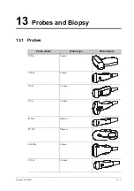
Page 195: ...perator s Manual 13 1 13 Probes and Biopsy 13 1 Probes Probe model Probe Type Probe Figure 7LT4s Linear L14 6s Linear C4 1s Convex C5 1s Convex P10 4s Phased P7 3Ts Phased L14 6Ns Linear C11 3s Convex...

Page 196: ...Manual 13 Probes and Biopsy SP5 1s Phased L16 4Hs Linear C6 2Gs Convex L20 5s Linear P8 3Ts Phased P4 2s Phased SC6 1s Convex V11 3Hs Convex L9 3s Linear P8 2s Phased P8 2Ts Phased Probe model Probe T...

Page 197: ...bes and Biopsy Operator s Manual 13 3 LAP13 4Cs Convex L14 5sp Linear L11 3VNs Linear L12 3RCs Linear L12 3VNs Linear C9 3Ts Convex i3P Phased i3PA Phased L14 3Ws Linear Probe model Probe Type Probe F...

Page 198: ...til it has been checked and re paired Before each use the outer surface of the portions of laparoscopic transducer which are intended to be inserted into a patient should be checked to ensure there ar...

Page 199: ...ing the deflection levers on the handle Make sure the deflection operates smoothly The up down and or left right deflection may after prolonged use develop an unwanted amount of free play In that case...

Page 200: ...position with the handle the distal tip will return to the zero position 13 1 2 Probe Functions by Part The basic structures and corresponding functions of probes are basically the same take the foll...

Page 201: ...onverts the electrical signal into an ultrasonic signal focusing the sound beams in a given direction meanwhile it receives the reflected ultrasonic signal and converts it into an electrical signal fo...

Page 202: ...guided biopsy procedure is performed Failure to do so may cause the probe and the needle guided bracket becomes a source of infection This section describes general procedures for operating the probe...

Page 203: ...em Examinations Wiping off the ultrasound gel Thoroughly cleaning the probe Drying the probe Disinfecting the probe Rinsing the probe Drying the probe Inspection after use Storage Biopsy procedure Ste...

Page 204: ...not be sufficient DO NOT use such a probe sheath The cover contains natural rubber latex and talc that can cause allergic reactions in some individuals DO NOT use an expired probe sheath Before using...

Page 205: ...656 4447 E mail info civco com http www civco com Refer to the probe dimensions listed the Probe Dimensions chapter to choose the necessary probe sheath type Perform the following procedure to install...

Page 206: ...use the probe to become deformed or damaged Observe the graph here carefully to immerse the probe Only soak parts of the probe below the strain relief Repeated disinfection will eventually damage the...

Page 207: ...our hospital policy and procedures for cleaning Perform the following procedure 1 Wear a pair of gloves to prevent infection 2 Disconnect the probe from the system If the sheath is used take off the s...

Page 208: ...r Observe the graph here carefully to perform disinfection Do not spray the strain relief on the connector end or the connector 4 Wipe away the residual disinfectant on the probe by using a piece of l...

Page 209: ...e residual disinfectant Repeat the operation twice Or follow the disinfectant manufacturer s instructions regarding rinsing 5 Dry the probe by wiping with a piece of clean disposable lint free soft cl...

Page 210: ...roughly by using a large amount of sterile distilled or softened water about 2 gallons at room temperature for about 30 s to remove the residual sterilant Repeat the operation twice Or follow the ster...

Page 211: ...00 hPa 1060 hPa C11 3s Operating 0 C 40 C 30 85 700 hPa 1060 hPa Storage and transportation 20 C 55 C 30 95 700 hPa 1060 hPa V11 3Hs Operating 0 C 40 C 20 85 700 hPa 1060 hPa Storage and transportatio...

Page 212: ...a 1060 hPa SC6 1s Operating 0 C 40 C 20 85 700 hPa 1060 hPa Storage and transportation 20 C 55 C 20 95 700 hPa 1060 hPa LAP13 4Cs Operating 0 C 40 C 20 85 700 hPa 1060 hPa Storage and transportation 2...

Page 213: ...he biopsy needle may fail to penetrate the target The incorrect biopsy may cause various side effects in the patient Use a needle guided bracket other than that provided Mount the needle guided bracke...

Page 214: ...ction The needle mark displayed on the ultrasound image does not indicate the actual position of the biopsy needle Therefore it should only be used as a reference Always monitor the relative positions...

Page 215: ...an be carried out 13 2 1 Needle guided Brackets Available Probe Needle Ultrasound beam Target Biopsy Target The biopsy needle appears to reach the target object in the image Dispersion of the ultrasou...

Page 216: ...cket before and after use Put on the sterile probe sheath before installing to the probe Confirm that the needle guided bracket is free of damage deformation stripping malfunction loose or missing par...

Page 217: ...hand Match the groove and tab with the tab and groove of the probe respectively Mount the bracket onto the probe c Screw the pinch nut of the needle guided bracket to ensure that the needle guided bra...

Page 218: ...k and push it into the groove above the angle block then clamp it tightly b Screw the block s nut to secure the block c Insert a biopsy needle with the same specification as that of the guiding block...

Page 219: ...terile probe sheath b Hold the probe by one hand select the proper needle guided bracket and hold it with the other hand Align the narrow end tab of the needle guided bracket with the groove of the pr...

Page 220: ...e guiding block a Select a proper guiding block and push it into the groove above the angle block and clamp it tightly b Insert a biopsy needle with the same specification as that of the guiding block...

Page 221: ...NGB 010 Metal needle detachable needle guided bracket Perform the following procedure 1 Install the needle guided bracket a Put on the sterile probe sheath 1 Guiding block 2 Guiding hole of the biopsy...

Page 222: ...le guided bracket to match with the tabs of the probe Set the needle guided bracket at the desired position turn tightly the knob of fixing needle guided bracket to fix the needle guided bracket d Che...

Page 223: ...edle guided bracket a Put on the sterile probe sheath b Connect the locating groove on the clamp with the two raised edges on the probe head and align the locating pit of the clamp with the convex poi...

Page 224: ...he groove to the tab of the probe Mount the bracket onto the probe c Screw the pinch nut of the needle guided bracket to ensure that the needle guided bracket is properly installed on the probe 2 Adju...

Page 225: ...secure the block c Insert a biopsy needle with the same specification as that of the guiding block into the guiding block hole 4 Release the needle from the bracket a Loosen the guiding block s nut an...

Page 226: ...onto the probe c Screw the pinch nut of the needle guided bracket to ensure that the needle guided bracket is properly installed on the probe 2 Adjust the needle angle to the proper shift as required...

Page 227: ...the needle from the bracket a Loosen the guiding block s nut and slightly move the guiding block in the direction of the needle s tail b Separate the residual part of the needle guide bracket and the...

Page 228: ...e needle angle to the proper shift as required a Loosen the angle pinch nut b Adjust the angle block to the desired level c Tighten the angle pinch nut 3 Insert the biopsy needle a Adjust the dial sca...

Page 229: ...uided bracket a Screw the pinch nut to release the needle guided bracket b Separate the bracket and the probe NGB 024 Metal needle detachable needle guided bracket Perform the following procedure 1 In...

Page 230: ...ix the bracket and the probe 2 Adjust the needle angle to the proper shift as required a Loosen the angle pinch nut b Adjust the angle block to the desired level c Tighten the angle pinch nut 3 Insert...

Page 231: ...type adjusting nut manually following the direction of the arrow The needle moves smoothly at the vertical direction due to its gravity 4 Release the needle from the bracket a Hold the probe Press the...

Page 232: ...ow The needle guided bracket is separate from the probe b Hold the probe and take out the bracket NGB 025 Metal needle undetachable needle guided bracket Perform the following procedure 1 Install the...

Page 233: ...serting into the location hole Turn the lower clamp against the intra cavity probe Tighten the nut to lock the biopsy arrow s direction 2 Remove the needle guided bracket a Hold the prober in the left...

Page 234: ...tch the locating groove with the tab of the probe Mount the bracket onto the probe c Tighten the pinch nut of the needle guided bracket to confirm that the needle guided bracket is properly installed...

Page 235: ...ll the lock pin and close the V shaped cover to fix the lock pin in the groove of the needle type adjusting base so as to install the needle into the guiding hole 4 Release the needle from the bracket...

Page 236: ...Put on the sterile probe sheath b Select the needle guided bracket and match the groove with the tab of the probe Mount the bracket onto the probe c Rotate the retaining nut to fix the bracket and th...

Page 237: ...edle a Hold the probe Press the biopsy needle to separate needle guided V shaped block from pressure position of the needle b Put the needle into the needle guided bracket and the needle leans to V sh...

Page 238: ...dle to separate the needle from pressure position of the needle b Separate the bracket and the probe from the needle 5 Remove the needle guided bracket a Rotate the clamping nuts of the needle guided...

Page 239: ...ed bracket to the tabs of the probe c Mount the bracket onto the probe and rotate the locking nut to fix the bracket 2 Insert the biopsy needle a Insert a biopsy needle into the guiding block hole b A...

Page 240: ...the probe b Hold the probe and take out the bracket NGB 044 Metal needle detachable needle guided bracket Perform the following procedure 1 Install the needle guided bracket 1 Right clamp 2 Groove 3...

Page 241: ...abs of the probe c Mount the bracket onto the probe and rotate the locking nut to fix the bracket 2 Adjust the needle angle to the proper shift as required a Loosen the depth pinch nut b Adjust the de...

Page 242: ...to the guiding block hole 4 Remove the needle guided bracket a Hold the probe and remove the needle b Loosen the guiding block nut and remove it from the guiding block fixing frame c Rotate the clampi...

Page 243: ...chable needle guided bracket 1 Angle adjusting block 2 Angle locking nut 3 Right clamp of the bracket 4 Left clamp of the bracket 5 Needle clamping cover 6 Needle shaped adjusting nut 7 Locking nuts o...

Page 244: ...he right and left sides to fix the bracket and the transducer Rotate the needle shaped adjusting nut to the ultimate position as shown in the figure 2 Adjust the needle angle to the proper shift as re...

Page 245: ...nut manually following the direction of the arrow The needle moves smoothly at the vertical direction due to its gravity 4 Release the needle from the bracket a Hold the probe Press the biopsy needle...

Page 246: ...ecurely in the correct position 2 Prepare a container filled with sterile water 3 Place the head of the probe in the sterile water and place a biopsy needle in the needle guide 4 When the biopsy needl...

Page 247: ...to adjust the needle direction display according to actual direction of needle insertion The iNeedle affecting region changes correspondingly b Select iNeedle again to exit 5 Scan to locate the target...

Page 248: ...r a period specified by the manufacturer 5 Immerse the needle guided bracket and all its parts fully in the cleaning solvent Wipe and wash the surface and connecting parts of the needle guided bracket...

Page 249: ...uch cleared by FDA 4 Place the packaged needle guided bracket inside a high temperature steam sterilizer and perform sterilization The sterilization parameters are 121 C and 30 minutes for a gravity d...

Page 250: ...long the line To use the Middle Line function of the ultrasound system a Change the mark position and by adjusting lithotripsy machine tools or patient posture to locate the stone center at the mark b...

Page 251: ...s by an experienced medical professional the eSpacial Navi system can achieve precision as high as 2 4 mm Place the magnetizer in the proper position to prevent the magnetizer from falling off or beco...

Page 252: ...e 2 Needle tip position in the ultrasound plane 3 Needle guidance trajectory 4 Scale of guideline 5 mm scale 3 4 2 1 1 Needle projection position in the ultrasound plane 2 Position at which the needle...

Page 253: ...and select Calibrate on the eSpacial Navi Needle menu Do not move the probe during the calibration 3 Magnetize a needle cap a Place an appropriate sterile needle cap length 3 5cm to 4 5cm diameter 7 m...

Page 254: ...pears Perform the following procedure 1 Hold the probe stably and put the needle close to the probe for connection After the needle and probe are successfully connected the system automatically calcul...

Page 255: ...rush because it may damage the magnetizer 3 Dry the magnetizer using a sterile cloth or gauze after rinsing Do not dry the magnetizer by heating it Table 13 7 Compatible disinfectants Trade Name Manuf...

Page 256: ...nt solution for the shortest time the manufacturer recommends Follow local regulations when selecting and using the disinfectant 3 Rinse the magnetizer with plenty of water about 2 gallons for at leas...

Page 257: ...ing 2 Tap to open the dialog box and select desired recording type 3 Tap Close to enter recording status 4 Press the user defined key for DVR and tap OK to start recording and the DVR icon displays as...

Page 258: ...the video and audio record 14 3 1 Replay on PC Connect the USB disk or optical disk with the file to the PC and open the file directly 14 3 2 Replay on the ultrasound system Perform the following pro...

Page 259: ...Daily Maintenance You are responsible for daily maintenance 15 1 1 Cleaning the System WARNING The display can be cleaned on power on status while the power is On by selecting Screen Lock to lock the...

Page 260: ...nside and outside of the holder should be wiped away using a cloth with a little soapy water and then air dried Cleaning the display NOTE Do not use chemical solvents acid or alkaline solution to clea...

Page 261: ...ning the peripherals Do the cleaning maintenance according to your actual peripheral configuration items which are not configured can be skipped Clip Content Description Color and B W video printer Fi...

Page 262: ...t or permit fluid to seep into connections or openings If you spill liquid on the main unit disconnect the power supply dry the main unit and contact your service personnel Never use abrasive material...

Page 263: ...sockets ventilation holes loudspeaker IO interface and power supply panel PDI Super Sani Cloth Wipe Bode Chemie Gmbh Mikrobac Tissues Wipe Diversey VIREX TB Solution Schulke Schulke mikrozid Sensitive...

Page 264: ...be cable Visually check to confirm that none of the connector pins are bent destroyed or falling off 15 1 5 Checking the Power Cable and Plug Visually check to confirm that there are no wrinkles crack...

Page 265: ...een turning off and restarting the system is too short wait at least 20 seconds Turn off the system and wait at least 1 minute then restart the system The display brightness or contrast may be imprope...

Page 266: ...This page intentionally left blank...

Page 267: ...t Router setting Wireless standard 802 11n Maximum transmission speed 300M Use AP access point setting Number of the devices connected to the same router 5 Target server setting Network is stable and...

Page 268: ...ans that the network is abnormal The reason for the failure may be disconnection or the system cannot obtain the IP address IP config is used for setting local network parameters which is also applied...

Page 269: ...em System anti interference Can be coexistent with other Wi Fi devices Network interruption alarm Network interruption is notified by disconnection icon and failure in transmission is notified by the...

Page 270: ...s from the network The transmission delay is too long Check if Mindray recommended wireless AP is used If not verify the AP effective transmission rate meets the throughput requirements of the connect...

Page 271: ...llowing procedure 1 Perform ordinary scanning procedure 2 Enter iScanHelper status tap in the top right corner of the screen and tap iScanHelper 3 Select the target view name in the menu and tap to se...

Page 272: ...e swing sweep techniques Scanning tips You can read tissue related anatomical information and adjacent tissue information here B 3 2 Single quad window Display You can zoom in the anatomic graphic ult...

Page 273: ...m data from the patient database or system supported image files and folders to the demonstration list For files and folders in the demonstration list the images in the directory and subdirectory are...

Page 274: ...This page intentionally left blank...

Page 275: ...Power Mode M Mode Turn on off M Mode PW Mode Turn on off PW Mode Freeze Freeze Image UnFreeze UnFreeze Image Clear Clear Dual Enter Dual Windows Format QSave QSave Update Update Full Image Turn on off...

Page 276: ...tart Measure Start Measurement Function Smart TTQA Start Smart TTQA Smart IVC Start Smart IVC Smart VTI Start Smart VTI Smart B lines Start Smart B lines Auto GA Start Auto GA Smart Nerve Start Smart...

Page 277: ...ose Patient Info Dialog Close Patient Info Dialog Open Probe Dialog Open Probe Dialog Close Probe Dialog Close Probe Dialog Open Review Dialog Open Review Dialog Close Review Dialog Close Review Dialo...

Page 278: ...This page intentionally left blank...

Page 279: ...An electrical safety inspection should be periodically performed every two years The safety analyzer is also an excellent troubleshooting tool for detecting abnormalities in line voltage and groundin...

Page 280: ...Earth Leakage Test Run an Earth Leakage test on the device being tested before performing any other leakage tests The following outlet conditions apply when performing the Earth Leakage test normal p...

Page 281: ...ngle Fault Condition reverse polarity with open earth Single Fault Condition LIMITS For ES 60601 1 100 A in Normal Condition 300 A in Single Fault Condition For IEC 60601 1 100 A in Normal Condition 5...

Page 282: ...Polarity Reversed Polarity LIMITS For BF applied parts 5000 A E 9 Patient Auxiliary Current Patient Auxiliary currents are measured between any selected Applied Part connector and the remaining Applie...

Page 283: ...se is necessary this equipment and the other equipment should be observed to verify that they are operating normally Use of accessories transducers and cables other than those specified or provided by...

Page 284: ...the require ments of CISPR Preventing conducted RF immunity Due to technological limitations the conducted RF immunity level are limited to 3Vrms level conducted RF interference above 3Vrms may cause...

Page 285: ...supply power instead of LV overhead power lines and use devices more than 30 m away from the residential environment or a structure as a radiation barrier NOTE The EMISSIONS characteristics of this eq...

Page 286: ...ntial use and does not provide adequate protection for radio reception RF interference caused by Class A equipment in a specific environment When connecting Class A equipment to a low voltage power su...

Page 287: ...Harmonic Emissions IEC 61000 3 2 Class A Voltage Fluctuations Flicker Emissions IEC 61000 3 3 Compliance Table F 3 GUIDANCE AND MINDRAY DECLARATION ELECTROMAGNETIC IMMUNITY The system is intended for...

Page 288: ...ins interruptions it is recommended that our product be powered from an uninterruptible power supply or a battery Power frequency 50 60 HZ magnetic field IEC 61000 4 8 30 A m 30 A m Power frequency ma...

Page 289: ...ined by an electromagnetic site survey should be less than the compliance level in each frequency range Interference may occur in the vicinity of equipment marked with the following symbol Radiated RF...

Page 290: ...1 58 1 58 100 20 5 5 For transmitters at a maximum output power not listed above the recommended separation distanced in meters m can be determined using the equation applicable to the frequency of th...

Page 291: ...nostic ultrasound instruments the possibility exists that such biological effects may be identified in the future Thus ultrasound should be used in a prudent manner to provide medical benefit to the p...

Page 292: ...s MI is an index that shows the possibility of the cavitations generation based on acoustic pressure and the value in which the peak rarefactional acoustic pressure is divided by the square root of th...

Page 293: ...stem stops transmitting acoustic power Default setting of acoustic power Selection of diagnostic applications is the most important factor for controlling ultrasound output The permissible level of in...

Page 294: ...ating modes frequency focal point positions overall depth and PRF The operating mode determines whether the ultrasound beam is scanning or non scanning Thermal bioeffect is closely connected to M mode...

Page 295: ...they were designed to assist in the implementation of the ALARA principle As an operator changes a given system control the potential effect of the change in output will be indicated However the Ther...

Page 296: ...diagnostic and monitoring equipment issued by IEC in 2015 IEC 62359 Ultrasonics Field characterization Test methods for the determination of thermal and mechanical indices related to medical diagnost...

Page 297: ...s 720 63 67 8 1770 50 L20 5s 98 43 24 1 2050 50 SC6 1s 111 9 76 7 28 2050 50 L14 5sp 95 1 70 8 25 4 2350 50 L9 3s 103 5 58 6 23 3 2050 50 P8 2Ts 1417 5 61 8 60 7 1800 50 LAP13 4Cs 560 66 5 51 2050 50...

Page 298: ...H 2 Operator s Manual H Probe Dimensions Length Height Max Width Max...

Page 299: ...Trans esoph non Card Musculo skeletal Conventional N N N N N N N Note 1 2 3 5 6 Musculo skeletal Superficial N N N N N N N Note 1 2 3 5 6 Intravascular Thoracic Pleural Specify N N N N N N Note 1 2 3...

Page 300: ...letal Conventional N N N N N N Note 1 2 3 5 Musculo skeletal Superficial Intravascular Thoracic Pleural Specify N N N N N N Note 1 2 3 5 Cardiac Cardiac Adult Cardiac Pediatric Intravascular Cardiac T...

Page 301: ...Musculo skeletal Conventional N N N N N N Note 1 2 3 5 Musculo skeletal Superficial Intravascular Thoracic Pleural Specify N N N N N N Note 1 2 3 5 Cardiac Cardiac Adult N N N N N N Note 1 2 3 5 Card...

Page 302: ...eletal Conventional N N N N N N Note 1 2 3 5 Musculo skeletal Superficial Intravascular Thoracic Pleural Specify N N N N N N Note 1 2 3 5 Cardiac Cardiac Adult Cardiac Pediatric Intravascular Cardiac...

Page 303: ...eletal Conventional Musculo skeletal Superficial Intravascular Thoracic Pleural Specify N N N N N N Note 1 2 3 5 Cardiac Cardiac Adult N N N N N N Note 1 2 3 5 Cardiac Pediatric N N N N N N Note 1 2 3...

Page 304: ...hral Trans esoph non Card Musculo skeletal Conventional N N N N N N Note 1 2 3 5 Musculo skeletal Superficial N N N N N N Note 1 2 3 5 Intravascular Thoracic Pleural Specify Cardiac Cardiac Adult Card...

Page 305: ...thral Trans esoph non Card Musculo skeletal Conventional Musculo skeletal Superficial Intravascular Thoracic Pleural Specify Cardiac Cardiac Adult Cardiac Pediatric Intravascular Cardiac Trans esoph C...

Page 306: ...eletal Conventional N N N N N N Note 1 2 3 Musculo skeletal Superficial N N N N N N Note 1 2 3 Intravascular Thoracic Pleural Specify N N N N N N Note 1 2 3 Cardiac Cardiac Adult Cardiac Pediatric Int...

Page 307: ...al Trans esoph non Card Musculo skeletal Conventional N N N N N N Note 1 2 3 6 Musculo skeletal Superficial N N N N N N Note 1 2 3 6 Intravascular Thoracic Pleural Specify Cardiac Cardiac Adult Cardia...

Page 308: ...Musculo skeletal Conventional N N N N N N Note 1 2 3 Musculo skeletal Superficial N N N N N N Note 1 2 3 Intravascular Thoracic Pleural Specify N N N N N N Note 1 2 3 Cardiac Cardiac Adult Cardiac Ped...

Page 309: ...Musculo skeletal Conventional N N N N N N N Note 1 2 3 6 Musculo skeletal Superficial N N N N N N N Note 1 2 3 6 Intravascular Thoracic Pleural Specify N N N N N N Note 1 2 3 Cardiac Cardiac Adult Ca...

Page 310: ...non Card Musculo skeletal Conventional N N N N N N Note 1 2 3 6 Musculo skeletal Superficial N N N N N N Note 1 2 3 6 Intravascular Thoracic Pleural Specify Cardiac Cardiac Adult Cardiac Pediatric Int...

Page 311: ...al Trans esoph non Card Musculo skeletal Conventional N N N N N N Note 1 2 3 6 Musculo skeletal Superficial N N N N N N Note 1 2 3 6 Intravascular Thoracic Pleural Specify Cardiac Cardiac Adult Cardia...

Page 312: ...oph non Card Musculo skeletal Conventional N N N N N N Note 1 2 3 6 Musculo skeletal Superficial N N N N N N Note 1 2 3 6 Intravascular Thoracic Pleural Specify N N N N N N Note 1 2 3 Cardiac Cardiac...

Page 313: ...Musculo skeletal Conventional N N N N N N Note 1 2 3 Musculo skeletal Superficial N N N N N N Note 1 2 3 Intravascular Thoracic Pleural Specify N N N N N N Note 1 2 3 Cardiac Cardiac Adult Cardiac Pe...

Page 314: ...Musculo skeletal Conventional N N N N N N Note 1 2 3 Musculo skeletal Superficial N N N N N N Note 1 2 3 Intravascular Thoracic Pleural Specify N N N N N N Note 1 2 3 Cardiac Cardiac Adult Cardiac Ped...

Page 315: ...Musculo skeletal Conventional N N N N N N Note 1 2 3 Musculo skeletal Superficial N N N N N N Note 1 2 3 Intravascular Thoracic Pleural Specify N N N N N N Note 1 2 3 Cardiac Cardiac Adult Cardiac Pe...

Page 316: ...eletal Conventional N N N N N N Note 1 2 3 6 Musculo skeletal Superficial N N N N N N Note 1 2 3 6 Intravascular Thoracic Pleural Specify N N N N N N Note 1 2 3 Cardiac Cardiac Adult Cardiac Pediatric...

Page 317: ...ethral Trans esoph non Card Musculo skeletal Conventional Musculo skeletal Superficial Intravascular Thoracic Pleural Specify Cardiac Cardiac Adult Cardiac Pediatric Intravascular Cardiac Trans esoph...

Page 318: ...oph non Card Musculo skeletal Conventional Musculo skeletal Superficial Intravascular Thoracic Pleural Specify N N N N N N Note 1 2 3 5 Cardiac Cardiac Adult N N N N N N N Note 1 2 3 4 5 7 Cardiac Ped...

Page 319: ...thral Trans esoph non Card Musculo skeletal Conventional Musculo skeletal Superficial Intravascular Thoracic Pleural Specify N N N N N N Note 1 2 3 5 Cardiac Cardiac Adult N N N N N N N Note 1 2 3 4 5...

Page 320: ...ethral Trans esoph non Card Musculo skeletal Conventional Musculo skeletal Superficial Intravascular Thoracic Pleural Specify Cardiac Cardiac Adult Cardiac Pediatric N N N N N N N Note 1 2 3 4 5 Intra...

Page 321: ...oph non Card Musculo skeletal Conventional N N N N N N N Note 1 2 3 5 Musculo skeletal Superficial Intravascular Thoracic Pleural Specify Cardiac Cardiac Adult N N N N N N N Note 1 2 3 4 5 Cardiac Ped...

Page 322: ...al Trans esoph non Card Musculo skeletal Conventional Musculo skeletal Superficial Intravascular Thoracic Pleural Specify N N N N N N Note 1 3 Cardiac Cardiac Adult N N N N N N Note 1 3 4 Cardiac Pedi...

Page 323: ...ral Trans esoph non Card Musculo skeletal Conventional Musculo skeletal Superficial Intravascular Thoracic Pleural Specify N N N N N N Note 1 3 Cardiac Cardiac Adult N N N N N N Note 1 3 4 Cardiac Ped...

Page 324: ...letal Conventional Musculo skeletal Superficial Intravascular Thoracic Pleural Specify Cardiac Cardiac Adult Cardiac Pediatric Intravascular Cardiac Trans esoph Cardiac N N N N N N N Note 1 4 5 Intra...

Page 325: ...letal Conventional Musculo skeletal Superficial Intravascular Thoracic Pleural Specify Cardiac Cardiac Adult Cardiac Pediatric Intravascular Cardiac Trans esoph Cardiac N N N N N N N Note 1 4 5 Intra...

Page 326: ...letal Conventional Musculo skeletal Superficial Intravascular Thoracic Pleural Specify Cardiac Cardiac Adult Cardiac Pediatric Intravascular Cardiac Trans esoph Cardiac N N N N N N N Note 1 4 5 Intra...

Page 327: ...oph non Card Musculo skeletal Conventional Musculo skeletal Superficial Intravascular Thoracic Pleural Specify Cardiac Cardiac Adult Cardiac Pediatric Intravascular Cardiac Trans esoph Cardiac Intra c...

Page 328: ...This page intentionally left blank...

Page 329: ......

Page 330: ...P N 046 023006 00 2 0...

Reviews: