13 - 34
Operator’s Manual
13 Probes and Biopsy
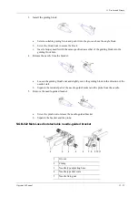
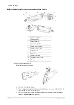
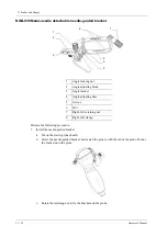
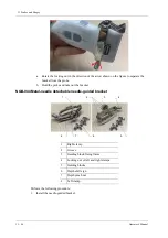
Perform the following procedure:
1.
Install the needle-guided bracket:
a.
Put on the sterile probe sheath.
b.
Hold the probe by one hand, select the proper needle-guided bracket, and hold it with the
other hand. Match the groove of the bracket with the tab of the probe. Amount the bracket
onto the probe.
c.
Screw the pinch nut of the needle-guided bracket to confirm that the needle-guided
bracket is properly installed on the probe.
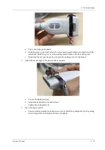
2.
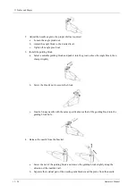
Adjust the needle angle to the proper shift as required:
a.
Loosen the angle pinch nut.
b.
Adjust the angle block to the desired level.
c.
Tighten the angle pinch nut.
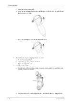
3.
Insert the biopsy needle:
a.
Adjust the dial scale to the required needle type shift, and then screw the needle fixing nut
to lock the dial scale. (To adjust the dial scale you have to loosen the needle fixing nut
first.)
b.
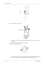
Pull the lock pin and close the V-shaped cover to fix the lock pin in the groove of the
needle type adjusting base, so as to install the needle into the guiding hole.
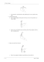
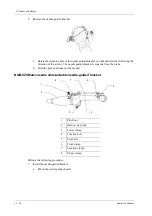
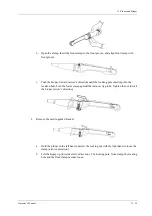
4.
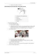
Release the needle from the bracket:
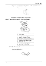
6
V-shaped cover
7
Angle adjusting base
8
Angle shift sign
9
Angle pinch nut
10
Angle block
11
Pinch nut
Summary of Contents for TE X
Page 2: ......
Page 15: ...Contents Operator s Manual ix I Indications for use I 1...
Page 16: ......
Page 24: ...This page intentionally left blank...
Page 110: ...This page intentionally left blank...
Page 168: ...This page intentionally left blank...
Page 188: ...This page intentionally left blank...
Page 266: ...This page intentionally left blank...
Page 274: ...This page intentionally left blank...
Page 278: ...This page intentionally left blank...
Page 298: ...H 2 Operator s Manual H Probe Dimensions Length Height Max Width Max...
Page 328: ...This page intentionally left blank...
Page 329: ......
Page 330: ...P N 046 023006 00 2 0...


