Physiological Signal 8-3
If the delay time is longer than a heart cycle, then the heart cycle between the delay time
is omitted, that is to say no trigger is occurred when R waveform is detected in the
duration.
8.1.2.2 Triggering Mode
This system supports single trigger.
Single Trigger:
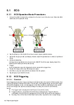
When an R waveform is detected, an image will be triggered after delay
time T1. The value of T1 can be changed in triggering status.
The operational steps are as follows:
1. Select exam mode.
2. Tap [Trig Mode] to turn on the trigger function.
3. Set the delay time T1.
8.1.3 ECG Review
8.1.3.1 Review Principle
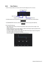
When an image is frozen, the ECG waveform where the image is triggered will be frozen at the
same time. When images are reviewed with the ECG electrodes connected, the ECG trace is the
reference for time.
After the images are frozen, all real time images are in the status of linked review.
8.1.3.2 Linked Review of ECG Signal, M/D Images and 2D Images
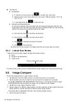
If the real (triggered) physio signal, M/D images and 2D image are frozen at the same time, then
they will be reviewed synchronously in the linked status.
8.2
Parameters description
The physio parameters are described as follows:
Parameter
Description
ECG Source
Select ECG source. Lead/External
Gain
Function: to set the amplitude of the trace.
Value: 0-30, in increments of 1.
Position (%)
Function: to set the vertical position of the both traces on the image
display.
Value: 0-100%, in increments of 5%.
Speed
Function: adjust the speed of the physio trace.
Range: 20-145 mm/s
Trig Mode
Turn on/off the triggering function.
Invert
Invert the ECG signal wave for observation.
T1
Function: to set the delay time T1 in Single trigger.
Summary of Contents for TE5
Page 1: ...TE7 TE5 Diagnostic Ultrasound System Operator s Manual Basic Volume ...
Page 2: ......
Page 6: ......
Page 12: ......
Page 24: ......
Page 36: ......
Page 54: ......
Page 110: ......
Page 115: ...Display Cine Review 6 5 6 Tap Return on the screen or tap Freeze to exit image compare ...
Page 120: ......
Page 124: ......
Page 156: ......
Page 174: ......
Page 192: ...12 18 Setup Select Advanced and do as follows Select MAPS and do as follows ...
Page 202: ...13 2 Probes and Biopsy C5 2s L12 4s L7 3s P4 2s L14 6s C11 3s L14 6Ns V11 3Ws P7 3Ts 7LT4s ...
Page 226: ...13 26 Probes and Biopsy NGB 034 NGB 035 ...
Page 250: ......
Page 272: ......
Page 276: ...A 4 Wireless LAN Tap Add Manually create a network profile to set ...
Page 282: ......
Page 318: ......
Page 322: ......
Page 323: ...P N 046 006959 07 1 0 ...


