5-12 Image Optimization
Operations
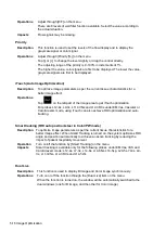
Adjust through [M Soften] on the menu.
The system provides 4 levels of M Soften adjustment: the bigger the value the
stronger the effect.
5.4
Color Mode Image Optimization
The Color mode is used to detect color flow information, and the color is designed to judge the
direction and speed of blood flow.
Generally, the color above the color bar indicates the flow towards the probe, while the color below
the color bar indicates the flow away from the probe. The brighter the color, the faster the flow
speed, while the darker the color, the slower the flow speed.
5.4.1 Basic Procedures for Color Mode Imaging
1. Select a high-quality image during B mode scanning, and adjust to position the area of interest
in the center of the B mode image.
2. Tap [Color] on the right side of the operating panel to enter Color mode.
3. Change the position and size of the Region of Interest (ROI).
4. Adjust the image parameters during scanning to obtain optimized images.
Tap [Image] to open the image menu. Adjust the parameters to optimize the image.
5. Perform other operations (e.g., measurement and calculation) if necessary.
5.4.2 Color Mode Image Parameters
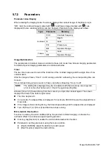
In Color mode scanning, the image parameter area in the top-left corner of the screen displays
the real-time parameter values as follows:
Parameter
F
G
PRF
WF
Meaning
Frequency Color Gain Pulse Repetition Frequency (PRF) Color Wall Filter
In Color mode, the acoustic power is synchronous with that of B mode. Adjustment of the
depth to the B mode image will lead to corresponding changes in Color mode image.
Summary of Contents for TE5
Page 1: ...TE7 TE5 Diagnostic Ultrasound System Operator s Manual Basic Volume ...
Page 2: ......
Page 6: ......
Page 12: ......
Page 24: ......
Page 36: ......
Page 54: ......
Page 110: ......
Page 115: ...Display Cine Review 6 5 6 Tap Return on the screen or tap Freeze to exit image compare ...
Page 120: ......
Page 124: ......
Page 156: ......
Page 174: ......
Page 192: ...12 18 Setup Select Advanced and do as follows Select MAPS and do as follows ...
Page 202: ...13 2 Probes and Biopsy C5 2s L12 4s L7 3s P4 2s L14 6s C11 3s L14 6Ns V11 3Ws P7 3Ts 7LT4s ...
Page 226: ...13 26 Probes and Biopsy NGB 034 NGB 035 ...
Page 250: ......
Page 272: ......
Page 276: ...A 4 Wireless LAN Tap Add Manually create a network profile to set ...
Page 282: ......
Page 318: ......
Page 322: ......
Page 323: ...P N 046 006959 07 1 0 ...


