background image

Parameter Menus

Operations

2 - 22

0070-10-0666-01

Trio™ Operating Instructions

2.4.1.4

ECG Monitoring

NOTE:

If an electro-surgical device is to be used on the patient, use 
the ESIS cable. Respiration from ECG is not available if the 
ESIS cable is used.

• Plug the patient cable firmly into the ECG connector on the 

Trio

. An ECG waveform will 

begin to display in the ECG waveform tile and the heart rate will be displayed in the 
ECG parameter tile to the right (see FIGURE 2-26).

• Select the desired 

ECG lead

 by turning the Navigator™ Knob to highlight the lead label, 

located in the upper left corner of the ECG waveform tile. Press the knob to enable 
scrolling through available leads. Lead II is the default setting.

• Select the desired 

ECG size

 by turning the Navigator™ Knob to highlight the current 

waveform size, located in the upper left corner of the ECG waveform tile. Press the knob 
to enable scrolling through available sizes. The default setting is 2 cm/mV.

NOTE:

Check ECG electrode sites every day for skin irritation. 
Replace electrodes as necessary.

Summary of Contents for Trio

Page 1: ...Operating Instructions 0070 01 0628 02_revD_Trio ops color indd 1 3 10 10 5 37 08 PM To Purchase Visit Avobus com or call 1 800 674 3655 ...

Page 2: ...Operating Instructions ...

Page 3: ...ET is a U S registered trademark of Masimo Corp Nellcor and OxiMax are U S registered trademarks of Nellcor Puritan Bennett Inc SatSeconds is a U S trademark of Nellcor Puritan Bennett Inc Copyright Mindray DS USA Inc 2008 All rights reserved Contents of this publication may not be reproduced in any form without permission of Mindray DS USA Inc ...

Page 4: ...d 2 5 Mark Event 2 6 Monitor Setup 2 6 Maintenance 2 13 Normal Screen 2 13 Parameter Menus 2 14 Electrocardiogram ECG Monitoring 2 14 Respiration Monitoring 2 29 SpO2 Monitoring 2 32 NIBP Monitoring 2 44 Temperature Monitoring 2 53 IBP Monitoring Optional 2 56 Alarms 2 63 Alarm Categories 2 63 Alarm Priorities 2 64 Alarm Setup Menus 2 64 Alarm Troubleshooting 2 75 Trends 2 76 Graphic Trend 2 76 Li...

Page 5: ...Kits and Accessories 5 6 Replacement Parts Trio Rolling Stand 5 6 Appendix 6 1 Specifications 6 1 Safety Standards 6 1 Safety Designations 6 2 Performance Accuracy 6 3 Environmental EMC 6 4 United States Food and Drug Administration Documents 6 4 Patient Parameter Specifications 6 5 ECG 6 5 ECG Performance Requirements 6 5 ANSI AAMI EC13 2002 Compliance 6 7 ECG Systole Detector and Heart Rate Mete...

Page 6: ...erating Instructions 0070 10 0666 01 iii Table of Contents Environmental and Safety Characteristics 6 22 Warranty Statements 6 28 Phone Numbers and How To Get Assistance 6 29 Manufacturer s Responsibility 6 29 ...

Page 7: ...iv 0070 10 0666 01 Trio Operating Instructions This page intentionally left blank To Purchase Visit Avobus com or call 1 800 674 3655 ...

Page 8: ...2 486 5 351 685 5 421 329 5 485 847 5 533 507 5 577 500 5 803 910 5 853 364 5 865 736 6 035 223 6 263 222 6 298 252 6 463 310 6 591 123 6 675 031 6 708 049 6 801 797 6 083 172 Re 35 122 Possession or purchase of this device does not convey any express or implied license to use this device with replacement parts which would alone or in combination with this device fall within the scope or one 1 or ...

Page 9: ...hould be placed equidistant from electrosurgery electrotome and the grounding plate to avoid cautery Ensure that wires from electrosurgery equipment and ECG cables do not become tangled WARNING The Trio monitor is intended for hospital use under the direct supervision of a licensed health care practitioner WARNING Ensure that the conductive parts of ECG electrodes do not contact other conductive p...

Page 10: ...lead wires for damage and ensure good skin contact prior to and during use Always use fresh electrodes and follow proper skin preparation techniques CAUTION Use of accessories transducers and cables other than those specified in the manual may result in increased Electromagnetic Emissions or decreased Electromagnetic Immunity of the Trio It can also cause delayed recovery after the discharge of a ...

Page 11: ...before instituting any therapy or intervention CAUTION Many patients suffer from poor peripheral perfusion due to hypothermia hypovolemia severe vasoconstriction reduced cardiac output etc These symptoms may cause a loss in vital sign readings CAUTION If the sensor or patient cable are damaged in any way discontinue use immediately To prevent damage do not soak or immerse the sensor in any liquid ...

Page 12: ...riction of hose etc will affect the accuracy and ability to measure the NIBP CAUTION When cleaning sensors do not use an excessive amount of liquid Wipe the sensor surface with a soft cloth dampened with a cleaning solution CAUTION Do not subject the sensor to autoclaving CAUTION Do not use sensors or cables that are damaged or have deteriorated CAUTION Replace the battery with one of the followin...

Page 13: ...ntly to ensure proper positioning alignment and skin integrity at least every eight 8 hours with the Adult and Pediatric re usable finger sensor check every four 4 hours for patients of poor perfusion or with skin sensitive to light check every 2 3 hours more frequent examinations may be required for different patients Change the sensor site if signs of circulatory compromise occur To Purchase Vis...

Page 14: ...ended for use in healthcare settings under the direct supervision of a licensed healthcare practitioner The intended use of the monitor is to monitor physiologic parameter data on adult and pediatric patients Physiologic data includes electrocardiogram invasive blood pressure non invasive blood pressure NIBP pulse oximetry heart rate derived from ECG SpO2 or NIBP respiration and temperature as sum...

Page 15: ...BF Equipment Equipotentiality Defibrillator Proof Type CF Equipment Alternating Current AC Alarm Off ON OFF only for a part of the equipment Alarm Mute Battery Charging Full Battery Indicator Data Output Low Battery Indicator Data Input Output No Battery in Unit NIBP Connection Non ionizing electromagnetic radiation A symbol designating compliance of the Trio monitor with the Medical Device Direct...

Page 16: ...Rate Pulse Rate Pulse Oximetry SpO2 Non Invasive Blood Pressure NIBP Respiration Rate and Temperature T1 Waveform displays are provided for ECG Pleth and Respiration An optional digital and waveform display for Invasive Blood Pressure IBP is available The optional built in thermal recorder provides hard copies of all digital data and waveforms as well as Tabular and Graphic Trend information The T...

Page 17: ...lor TFT LCD 4 trace erase bar refresh ECG 3 or 5 Lead I II III aVR aVL aVF V ECG Cascade ESIS Capability 3 or 5 Lead Blood Pressure Non Invasive Blood Pressure SpO2 Masimo SET SpO2 Nellcor OxiMax SpO2 Respiration Impedance Temperature One YSI 400 channel Trend Tabular and Graphic Trends up to 24 hours Power Internal isolated power module Sealed lead acid battery or Lithium Ion battery Printing Two...

Page 18: ... Product Description Front Panel 1 1 Front Panel FIGURE 1 1 Front View of Monitor 1 Alarm Light Illuminates when an alarm is triggered 2 Display 8 4 color TFT LCD 800 x 600 resolution 3 Front Panel Keypad Navigator Knob and dedicated quick action keys 1 2 3 ...

Page 19: ...er this LED does not illuminate When a low battery condition exists this LED flashes at a constant rate 3 AC POWER INDICATOR A green LED that is illuminated when AC power is present 4 NIBP Press this key to begin a NIBP measurement During a measurement press this key to cancel the measurement and deflate the cuff 5 PRINT Press this key to initiate a real time printout of numeric data and selected ...

Page 20: ...ted menu Once a menu is displayed rotate the knob to highlight one of the items listed Press the knob to select the highlighted item When it is not highlighted the MENU icon will display as white text on the footer background with a white outline When all other menu targets are not highlighted they will be displayed in the colors that are defined in the PARAMETER COLORS menu When navigating within...

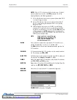
Page 21: ...re enables the user to save the customized settings The display is divided into the following areas see FIGURE 1 3 1 Demographics 2 Technical Alarms 3 Waveform Data Menus 4 Parameter Tiles 5 Status Bar FIGURE 1 3 Main Display 1 Demographics The demographics area displays the following information Bed Bed number 6 characters maximum First Name First name of the patient 10 characters maximum Last Na...

Page 22: ...F the display will show four 4 waveforms ECG SpO2 PLETH IBP and Respiration RESP If the ECG cascade is set to ON then the cascaded ECG will replace the SpO2 PLETH waveform ECG Lead Gain and Filter are displayed in the upper left corner of the main display The IBP waveform label is displayed in the upper left corner of the IBP waveform window The waveforms are refreshed according to the rate design...

Page 23: ...l adjust accordingly The numeric data is displayed at fixed positions within each parameter tile see FIGURE 1 4 FIGURE 1 4 Parameter Tiles A ECG PACER Display ON or OFF Heart Rate HR Pulse Rate PR Unit bpm B NIBP Systolic Diastolic Mean Units mmHg or kPa Interval Display CONT 1min 2min 3min 4min 5min 10min 15min 30min 1HR 2HRS 4HRS OFF Elapsed Time Display ET C SpO2 Pulse Rate PR Unit bpm SpO2 Uni...

Page 24: ... in the lower right portion of the display when the unit is operated by battery power When the batteries are fully charged the color will be filled in as shown Battery Low The battery low icon appears in the lower right portion of the display when the unit is operating on battery power When the batteries are running low color appears only on the right portion of the indicator No Battery in Unit Th...

Page 25: ...el see FIGURE 1 5 FIGURE 1 5 Left Side Panel 1 Handle bedrail hook Handle with integrated bedrail hook 2 Recorder Optional Two trace thermal strip chart recorder 3 Recorder Power LED A green LED that indicates that the recorder is receiving power 4 Battery compartment The housing for the optional user replaceable rechargeable battery sealed lead acid or Lithium Ion 2 4 1 3 To Purchase Visit Avobus...

Page 26: ...SpO2 sensor to the monitor 2 Optional IBP A six pin male receptacle used for an IBP connection 3 ECG Receptacle A six position female receptacle used to attach a 3 or 5 Lead ECG cable 4 T1 Receptacle A standard 1 4 phone jack is used to mate with the YSI series 400 temperature probe 5 NIBP Quick Connect Rectus Pneumatic Fitting This pneumatic fitting is used to attach the NIBP hose to the unit Qui...

Page 27: ...ck that is used for software upgrades NOTE This port should not be used while monitoring a patient 2 Analog Output AO1 The analog signal output connector may be used with a oscillometer pen recorder or other external devices see section 4 The connector is a BNC jack NOTE After connecting any external device to the Analog Output verify that leakage currents do not exceed accepted limits CS1 SP1 AO1...

Page 28: ...For additional information see P N 0070 00 0307 The VGA output connector provides connectivity to a medical grade remote display The connector is a 15 position D Shell connector Connection to this port should be made with the monitor power OFF Power ON the monitor after powering ON the remote display NOTE After connecting any external device to the Serial Port or the VGA Output verify that leakage...

Page 29: ...Rear Panel General Product Description 1 14 0070 10 0666 01 Trio Operating Instructions This page intentionally left blank ...

Page 30: ... Check all monitor functions for proper operation NOTE If the monitor is damaged contact the biomedical engineer of the hospital or Customer Service immediately 2 1 1 Setting up Patients 1 Turn the monitor ON using the POWER key on the front panel 2 Remove all of the previous patient data except BED and SIZE as follows a Use the Navigator Knob to select the MENU icon located in the bottom right co...

Page 31: ...rn to the normal screen 2 2 Menus The Trio menu system is accessed using the Navigator Knob The flexibility of the menu system enables the configuration of various features including the monitored parameters waveform sweep speed audio volume and parameter colors The MENU icon located in the bottom right corner of the display provides access to the SYSTEM MENU The parameter menu label in each param...

Page 32: ...nd NORMAL SCREEN For the default settings of all menu selections refer to section 3 0 Defaults Use the Navigator Knob to select the MENU icon in the lower right corner of the screen The SYSTEM MENU FIGURE 2 1 is displayed From the SYSTEM MENU select a submenu FIGURE 2 1 System Menu 2 3 1 Patient Setup Select PATIENT SETUP from the SYSTEM MENU The PATIENT SETUP menu FIGURE 2 2 is displayed FIGURE 2...

Page 33: ...le SIZE Select to enter the patient size choices are ADU for Adult and PED for Pediatric BIRTH Select to enter the patient date of birth format year month day HT cm Select to enter the patient height WT kg Select to enter the patient weight PATIENT DISCHARGE Select to discharge the current patient and admit a new patient Selecting PATIENT DISCHARGE opens the confirmation dialog box FIGURE 2 3 The ...

Page 34: ... Panel Keypad to exit the menu and return to the normal screen Entering the GENDER SIZE BIRTH DATE HEIGHT and WEIGHT Use the Drop Down and Spin Edit Boxes to enter the GENDER SIZE BIRTH HT and WT information proceed as follows NOTE Setting the SIZE will automatically select all user defined defaults for that patient size 1 Select the PATIENT SETUP menu and use the Navigator Knob to scroll to the i...

Page 35: ...Menu To mark an event use the Navigator Knob to select EVENT A B C or D Once an event is marked the symbol appears in the event box To cancel the selection move the cursor to the event and press the knob again Select PREVIOUS MENU to save the marked event exit the MARK EVENT menu and return to the previous menu Select NORMAL SCREEN from the menu or the Front Panel Keypad to save the marked event t...

Page 36: ...e Setup From the MONITOR SETUP menu select the TIME SETUP menu to modify the time and date settings displayed on the monitor see FIGURE 2 6 The TIME SETUP menu allows the user to set the YEAR MONTH DAY HOUR MINUTE and SECOND Use the Navigator Knob to adjust settings accordingly Select PREVIOUS MENU to exit the TIME SETUP menu and return to the previous menu Select NORMAL SCREEN from the menu or th...

Page 37: ...ayed on the printout as WAVEFORM 1 and WAVEFORM 2 Only waveforms that are displayed on screen are available for selection Available parameter waveform selections include ECG ECG waveform SpO2 SpO2 Plethysmogram IBP IBP waveform optional RESP Respiration waveform OFF No display for this waveform NOTE Two 2 waveforms can not be set to the same parameter Attempting to set a duplicate parameter will c...

Page 38: ...etween the start of recorder activations The following 10 selections are available OFF 10min 20min 30min 40min 50min 1HR 2HRS 3HRS and 4HRS The system will initiate the print operation according to the selected time interval All interval waveform printouts are 8 seconds in length NOTE A real time printout based on TIME as described in the previous menu takes priority over a printout based on INTER...

Page 39: ...l screen FIGURE 2 8 Analog Setup Menu 2 3 5 5 Module Setup MODULE SETUP allows the user to customize the display by selecting the parameters to be monitored Select MODULE SETUP from the MONITOR SETUP menu see FIGURE 2 9 FIGURE 2 9 Module Setup Menu Select the parameters to monitor by using the Navigator Knob to select the item to be displayed A check mark will be displayed in the box next to each ...

Page 40: ...ting MODE 2 provides a basic view angle and a smooth wave This mode should be used when the Trio is wall mounted and being viewed from below 1 Select TRACE SETUP from the MONITOR SETUP menu The TRACE SETUP menu FIGURE 2 10 is displayed FIGURE 2 10 Trace Setup Menu 2 Use the Navigator Knob to select each parameter waveform a check mark in the box next to a parameter indicates that it has been selec...

Page 41: ...Defaults 1 Select RESTORE DEFAULTS from the MONITOR SETUP menu The RESTORE DEFAULTS menu FIGURE 2 12 is displayed FIGURE 2 12 Restore Defaults Menu The RESTORE DEFAULTS menu allows the user to perform the following two 2 functions The RESTORE USER DEFAULTS function allows the user to revert back to a previously saved group of monitor settings for the selected patient size The RESTORE FACTORY DEFAU...

Page 42: ...nt size 1 Select SAVE CURRENT from the MONITOR SETUP menu The confirmation dialog box in FIGURE 2 13 is displayed 2 Select YES to replace the existing user defined configuration with the current customized settings Select NO to cancel the task FIGURE 2 13 Confirmation Dialog Box 2 3 6 Maintenance Refer to the Trio Service Manual Part Number 0070 00 0627 03 for details on maintenance functions 2 3 ...

Page 43: ...ctrodes do not contact other conductive parts including earth ground CAUTION To avoid possible damage to the Trio use only approved ECG cables and approved accessories CAUTION Line isolation transients may resemble actual cardiac waveforms thus inhibiting heart rate alarms Check lead wires for damage and ensure good skin contact prior to and during use Always use fresh electrodes and follow proper...

Page 44: ...E If using the snap type electrode wires attach the electrode patch to the lead wire before placing patch on the patient 2 Attach the electrode patch to the skin at the prepared site Smooth the electrode patch down in a circular motion to ensure proper skin contact If using soft gel electrodes never push down directly over the contact gel medium as this may displace the gel and cause monitoring ar...

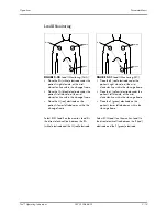
Page 45: ...ission IEC Standard 3 wire Lead Sets Standard 3 wire lead sets include 3 ECG leads I II and III Only 1 lead is monitored FIGURE 2 14 3 wire Lead Placement AHA FIGURE 2 15 3 wire Lead Placement IEC Place the RA white electrode under the patient s right clavicle at the mid clavicular line within the rib cage frame Place the LA black electrode under the patient s left clavicle at the mid clavicular l...

Page 46: ... right abdomen within the rib cage frame Place the V brown electrode in one of the V lead positions V1 V6 depicted in the following section Place the R red electrode under the patient s right clavicle at the mid clavicular line within the rib cage frame Place the L yellow electrode under the patient s left clavicle at the mid clavicular line within the rib cage frame Place the F green electrode on...

Page 47: ...stal space on the left sternal border V3 Place the electrode midway between V2 and V4 on a line joining these 2 locations C3 Place the electrode midway between C2 and C4 on a line joining these 2 locations V4 Place the electrode at the fifth intercostal space on the mid clavicular line C4 Place the electrode at the fifth intercostal space on the mid clavicular line V5 Place the electrode at the fi...

Page 48: ...eft abdomen within the rib cage frame Select ECG Lead II on the monitor Lead II is the direct electrical line between the RA white electrode and the LL red electrode Place the R red electrode under the patient s right clavicle at the mid clavicular line within the rib cage frame Place the L yellow electrode under the patient s left clavicle at the mid clavicular line within the rib cage frame Plac...

Page 49: ...ode and the LA black electrode Select ECG Lead II for MCL6 monitoring Lead II is the direct electrical line between the RA white electrode and the LL red electrode Place the R red electrode under the patient s left clavicle at the mid clavicular line within the rib cage frame Place the L yellow electrode on the right sternal border at the fourth intercostal space within the rib cage frame Place th...

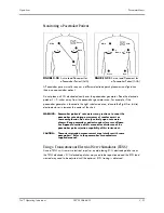
Page 50: ...st or some arrhythmias Do not rely entirely upon rate meter alarms Keep pacemaker patients under close surveillance See Appendix section of this manual for disclosure of the pacemaker pulse rejection capability of this instrument CAUTION Thoracic respiration measurement may interfere with some pacemakers Refer to the pacemaker s manufacturer supplied manual Using a Transcutaneous Electrical Nerve ...

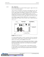
Page 51: ...ECG parameter tile to the right see FIGURE 2 26 Select the desired ECG lead by turning the Navigator Knob to highlight the lead label located in the upper left corner of the ECG waveform tile Press the knob to enable scrolling through available leads Lead II is the default setting Select the desired ECG size by turning the Navigator Knob to highlight the current waveform size located in the upper ...

Page 52: ...used when the unit is set to 3 lead mode only Lead I II and III are operable 2 ECG Size The selectable waveform sizes are 0 25 0 5 1 and 2 A waveform scale bar displays on the right side of each ECG channel The height of the waveform bar is directly proportional to the waveform amplitude 3 ECG Filter The available filter modes are MONITOR EXTENDED and SURGERY These modes offer different frequency ...

Page 53: ...se as well as the extreme amount of high frequency noise generated by an Electro Surgical Device However the resultant waveform lacks detail SURGERY mode is not recommended for Paced patients The Pacer pulse can become sufficiently distorted so that it could be mistaken for a QRS complex whereby a heart rate would continue to be counted even though the patient could be in cardiac arrest NOTE Durin...

Page 54: ...HR alarm See Heart Rate Alarm Limits on page 2 27 HR ALM LO Allows the user to set the lower limit of the HR alarm See Heart Rate Alarm Limits on page 2 27 SOURCE Determines the source of heart rate An audible tone is generated when a heart beat is detected from the selected source The selections are ECG SpO2 and AUTO NOTE When heart rate is being measured a heart rate source label SOURCE XXXX is ...

Page 55: ...lor as the NIBP numeric waveform data NOTE Heart rate that is sourced through NIBP will time out according to the NIBP DISPLAY TIMEOUT rules described on page 2 49 PACER To be used when a patient has a pacemaker This should be used whether the pacemaker is active or is in standby mode The ON selection will mark each detected pacemaker signal on the ECG waveform CASCADE ECG cascade extends the ECG ...

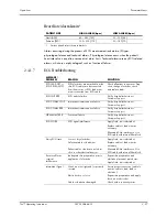
Page 56: ...ermittent communication failure Notify hospital technician or Customer Support ECG COMM ERR Intermittent communication failure Notify hospital technician or Customer Support HR ALM LMT ERR Functional failure Notify hospital technician or Customer Support ECG NOISE ECG signal interference Apply fresh moist electrodes Replace cable or lead wires as necessary Eliminate 60 Hz interference Use ECG cabl...

Page 57: ...old Apply fresh moist electrodes Skin improperly prepped Abrade the skin and repeat skin preparation This could be the patient s normal QRS complex Verify with a 12 lead electro cardiogram Electrode positioned over a bone or muscle mass Reposition electrodes No ECG waveform Size not set properly Readjust the ECG wave gain as required Refer to ECG Lead Size and Filter Settings on page 2 23 for inst...

Page 58: ...o reposition the ECG electrodes to optimize respiratory signal Prep the patient s skin for electrode placement as described in the ECG section of this manual See section 2 4 1 2 4 2 2 Respiration Setup Menu Accessing the Respiration Menu To access the RESP SETUP menu select RESP from the RESP parameter tile using the Navigator Knob The RESP SETUP menu FIGURE 2 29 is displayed Use the Navigator Kno...

Page 59: ...es automatic printing during a RESP alarm condition Choose ON to enable printing upon RESP alarm Choose OFF to disable printing upon RESP alarm ALM HI Allows the user to set the upper limit of the RESP alarm See Respiration Rate Alarm Limits on page 2 30 ALM LO Allows the user to set the lower limit of the RESP alarm See Respiration Rate Alarm Limits on page 2 30 SWEEP Adjusts the speed of the RES...

Page 60: ...eathing shallow or turned on side Change lead selection Scale set inappropriately Change Respiration scale ARTIFACT Respiration value equals the heart rate Check patient notify physician Shallow breathing Change Respiration scale Adjust leads Cessation of breathing Check patient notify physician No Respiration Waveform Cable not connected Check cable connections ESIS cable in use Use non ESIS cabl...

Page 61: ...bed in section 2 4 3 2 FIGURE 2 31 SpO2 Parameter Tile The corresponding plethysmogram is a waveform representation of the arterial oxygenation and pulse detection The pleth waveform is automatically scaled and no adjustment can be made to its size The SpO2 results are updated once every second Traditional pulse oximetry determines SpO2 by passing red and infrared light into a capillary bed and me...

Page 62: ...ent finger or toe Ensure that the sensor is properly aligned and securely applied Use a new sensor Move the sensor to a less active site Use a type of sensor that tolerates some patient motion Ensure that the sensor and site are clean non greasy Remove nail polish and fungus Calibration The oximetry sub system incorporates automatic calibration mechanisms No other calibration is required Auto Scal...

Page 63: ...ve ambient light In such cases cover the sensor site with opaque material excessive patient movement venous pulsations electro surgical interference placement of a sensor on an extremity that has a blood pressure cuff arterial catheter or intra vascular line nail polish or fungus CAUTION In certain situations in which perfusion and signal strength are low such as in patients with thick or pigmente...

Page 64: ...er to instructions included with each SpO2 sensor and cable for proper placement and use 1 Select an SpO2 sensor that is appropriate for the size of the patient 2 Attach the connector of the SpO2 sensor to the SpO2 extension cable 3 Attach the SpO2 sensor to the patient s finger or other appropriate site 4 Orient the connector on the end of the SpO2 extension cable so that the Masimo SET logo is f...

Page 65: ...iority 1 alarms are considered the most serious ALM PRINT Enables or disables automatic printing during an SpO2 alarm condition Choose ON to enable printing upon SpO2 alarm Choose OFF to disable printing upon SpO2 alarm SPO2 ALM HI Allows the user to set the upper limit of the SpO2 alarm See Masimo SET SpO2 Alarm Limits on page 2 38 SPO2 ALM LO Allows the user to set the lower limit of the SpO2 al...

Page 66: ... quality and patient motion In most cases where there is some level of patient motion present the normal sensitivity setting is appropriate If patient motion is limited the high sensitivity setting can be used High sensitivity should be used when it is difficult to get a reading on a patient with low perfusion This mode will compromise the probe off detection Selections are Normal and High SENSOR ...

Page 67: ...ug the sensor into the monitor or the extension cable SpO2 Interference Noise detected on the pulse signal prevents pulse discrimination Decrease patient motion Check sensor SpO2 Pulse Search Hardware settings are being adjusted in order to discriminate a pulse waveform Wait several seconds for saturation value to be displayed If it does not display do one of the following Change to site where pul...

Page 68: ...arm occurs at 5 seconds because 5 X 5 seconds 25 SatSeconds The alarm continues for another 2 seconds When the SpO2 measurement returns to within the alarm limits the SatSeconds indicator clears empties counter clockwise in the same amount of time that it took for the SatSeconds alarm condition to be acquired The clear time is equivalent to the acquire time Nellcor s SatSeconds Alarm Management te...

Page 69: ... Setup Menu Accessing the Nellcor SpO2 Setup Menu To access the NELLCOR SPO2 SETUP menu select SpO2 from the SpO2 parameter tile using the Navigator Knob Once in the NELLCOR SPO2 SETUP menu use the Navigator Knob to adjust settings To close the menu select NORMAL SCREEN from the menu or the Front Panel Keypad Nellcor SpO2 Setup Menu Selections ALM PRIORITY Enables the user to select the priority o...

Page 70: ... SpO2 Sensor OFF condition The selections are ON and OFF If ON is selected then the audio beep alarm will sound when an SpO2 Sensor OFF condition occurs If OFF is selected then the audio beep alarm will not sound when an SpO2 Sensor OFF condition occurs SAT SECONDS Controls pulse oximetry nuisance alarms see section 2 4 3 2 for details on SatSeconds features The selections are OFF 10 25 50 or 100 ...

Page 71: ... the sensor into the monitor or the extension cable SPO2 PULSE SEARCH Hardware settings are being adjusted in order to discriminate a pulse waveform Wait several seconds for saturation value to be displayed If it does not display do one of the following Change to site where pulse is stronger if patient is vasoconstricted Change or readjust sensor if loose SPO2 CHECK SENSOR SpO2 sensor may be defec...

Page 72: ...70 10 0666 01 2 43 Operations Parameter Menus SPO2 EXCEED SpO2 value exceeds the measurement range Check patient notify physician PR EXCEED PR value exceeds the measurement range Check patient notify physician MESSAGE REASON ACTION ...

Page 73: ...ent CAUTION Any condition which may affect the regularity and strength of arterial pressures such as patient movement cardiac arrhythmias restriction of hose etc will affect the accuracy and ability to measure the NIBP CAUTION Observe caution on all patients Pediatrics and Adults when NIBP is set to the Continuous mode and the 1 minute Interval When the NIBP Continuous interval is chosen the Trio ...

Page 74: ...neously high readings Selection of the cuff size should be based on the circumference of the patient s limb The design dimensions of the cuffs and their intended use are based on recommendations made by the American Heart Association NOTE Use only the authorized blood pressure cuffs and hoses listed in section 5 0 Accessories with the Trio 2 Attach the NIBP cuff to the NIBP extension hose 3 Attach...

Page 75: ...If a measurement cannot be obtained the Trio automatically reinflates the cuff to 30 60 mmHg higher than the initial inflation pressure but will not exceed the maximum cuff pressure listed in the NIBP Sub System Functional Requirements section 6 2 6 5 The patient should remain still to avoid the introduction of unnecessary motion artifact After the cuff pressure drops below the diastolic pressure ...

Page 76: ...played during the measurement of NIBP MESSAGE CAUSE Cont measuring Displayed during Continuous measuring Auto measuring Displayed during Automatic Interval measuring Please start Displayed after selecting an INTERVAL in the NIBP SETUP menu Measurement over Displayed after an NIBP measurement has been manually stopped by pressing the NIBP key during the measurement ET 5min CUFF 100 NIBP mmHg 108 70...

Page 77: ...the alarm If the alarm is set to OFF the alarm OFF symbol will display to the right of NIBP on the screen The NIBP alarm is activated when the blood pressure value exceeds set high or low NIBP values ALM PRIORITY Allows the user to select the priority of the NIBP alarm Choices are 1 2 and 3 Priority 1 alarms are considered the most serious ALM PRINT Enables or disables automatic printing during a ...

Page 78: ...e user to select the interval at which NIBP measurement will automatically initiate It also allows the user to turn the automatic measurement OFF The selections are CONT continuous 1min 2min 3min 4min 5min 10min 15min 30min 1HR 2HRS 4HRS and OFF DISPLAY TIMEOUT Allows the user to select the interval at which the NIBP measurement will time out from the display The selections are 15min 30min 45min a...

Page 79: ...tion and support the limb in such a way as to minimize stretching of affected nerves as well as weight exertion on affected nerves Avoid cuff placement that applies pressure on the ulnar nerve Cuff tubing should not exit the cuff over the course of the ulnar nerve at the elbow Select a measurement interval that provides adequate venous drainage during cuff deflation Periodically inspect the limb b...

Page 80: ...hey are calm A kicking crying baby may disturb or dislodge the cuff causing noise within the system and as a result yielding unstable blood pressure readings If necessary hold the cuffed limb steady but do not impede circulation do not hold onto the cuff and do not pat the cuffed limb to comfort the child 2 Try placement on the baby s calf Irritable newborns will react to cuff pressure on the arm ...

Page 81: ...DED NIBP value exceeds the upper measurement limit Check patient notify physician EXCESSIVE MOTION and or SIGNAL SATURATED Monitor is detecting too much motion and or noise to obtain a reading Instruct patient to remain still during the NIBP cuff reading If patient is agitated consider trying to take the pressure at a later time when patient is calm OVER PRESSURE Pressure has exceeded the specifie...

Page 82: ...te checks reapplication and moving of the probes 4 Check the probe site frequently for position ensuring good contact with the site chosen For example check the skin probe frequently to ensure good skin contact NOTE A self test of the temperature measurement is performed automatically once per hour during the monitoring period The test procedure lasts approximately 2 seconds and does not affect th...

Page 83: ... or low TEMP values ALM PRIORITY Enables priority selection for the TEMP alarm Choices are 1 2 and 3 Priority 1 alarms are considered the most serious ALM PRINT Enables or disables automatic printing during a TEMP alarm condition Choose ON to enable printing upon TEMP alarm Choose OFF to disable printing upon TEMP alarm TEMP ALM HI Allows the user to set the upper limit of Temperature 1 alarm See ...

Page 84: ...le is properly connected check connection between probe and cable T1 ALM LMT ERR Functional failure Notify hospital technician or Customer Support TEMP ALM LMT ERR Functional failure Notify hospital technician or Customer Support T1 EXCEED Temperature value of channel exceeds measurement range Check patient notify physician TEMP EXCEED Temperature value of channel exceeds measurement range Check p...

Page 85: ...OTE For CVP RAP LAP and ICP only the Mean Arterial Pressure is measured NOTE An arterial pressure catheter should not be used on a limb that is being utilized for any other medical procedure For example an IV catheter NIBP measurement or SpO2 readings NOTE Please refer to pressure transducer manufacturer s instructions for suggested procedures and maintenance Follow hospital policy regarding cathe...

Page 86: ...ressure Monitoring 1 Plug the pressure transducer cable into the IBP connector on the side panel 2 Connect the catheter line with flushing device to a pressure transducer making sure the tubing is free of air bubbles 3 Zero the pressure transducer Adjust the transducer to the mid axillary line of the patient s chest heart level Turn the transducer stopcock to open the transducer vent to atmosphere...

Page 87: ...Knob to scroll through the various labels Choices are ART PA CVP RAP LAP and ICP Press the Navigator Knob to select the desired label 2 4 6 2 IBP Setup Menu FIGURE 2 44 IBP Setup Menu Accessing the IBP Setup Menu To access the IBP SELECT menu select IBP from the IBP parameter tile using the Navigator Knob Once in the IBP SELECT menu use the Navigator Knob to open the IBP SETUP menu To close the me...

Page 88: ...ows the user to set the upper limit of the Systolic IBP alarm See IBP Alarm Limits on page 2 61 SYS ALM LO Allows the user to set the lower limit of the Systolic IBP alarm See IBP Alarm Limits on page 2 61 MEAN ALM HI Allows the user to set the upper limit of the Mean Arterial Pressure IBP alarm See IBP Alarm Limits on page 2 61 MEAN ALM LO Allows the user to set the lower limit of the Mean Arteri...

Page 89: ...on the display without clipping or cutting off any part To adjust the scale use the Navigator Knob to scroll to the desired area of the scale and select the desired limit Three 3 scale choices are available HI LO and MID MID allows the user to establish a reference line between the HI and LO set limits of the scale FIGURE 2 45 IBP Scale Adjust Menu RESTORE DEFAULTS Allows the user to restore the I...

Page 90: ... HIGH mmHg MEAN LOW mmHg DIA HIGH mmHg DIA LOW mmHg ART Adult 5 300 180 0 150 80 5 150 100 5 100 40 5 140 100 0 120 50 Ped 5 240 150 0 130 70 5 100 80 5 50 30 5 100 80 0 95 40 PA Adult 5 300 180 0 150 80 5 150 100 5 100 40 5 140 100 0 120 50 Ped 5 240 150 0 130 70 5 100 80 5 50 30 5 100 80 0 98 40 CVP Adult n a n a 5 150 10 5 100 0 n a n a Ped n a n a 5 100 10 5 50 0 n a n a RAP Adult n a n a 5 15...

Page 91: ... error Notify hospital technician or Customer Support IBP ALM LMT ERR Functional failure Notify hospital technician or Customer Support IBP SYS EXCEED Systolic pressure value exceeds measurement range Check patient notify physician IBP DIA EXCEED Diastolic pressure value exceeds measurement range Check patient notify physician IBP MAP EXCEED Mean arterial pressure value exceeds measurement range C...

Page 92: ...t s medical condition These alarms occur when the patient s vital signs are equal to or exceed set alarm limits Alarm limits are available for Heart Rate HR Systolic SYS blood pressure Diastolic DIA blood pressure Mean Arterial Pressure MEAN Respiration RESP SpO2 and Temperature TEMP All of these alarm limits have an OFF selection with the exception of SpO2 alarm low Each of these parameters has d...

Page 93: ...c value of the alarming parameter displays in black text on a yellow background and does not flash The alarm light will be amber and does not flash The audio alert cycles once every 25 seconds All physiological alarms can be changed by the clinician Technical alarm priorities are preset in the system and can not be changed The alert message for technical alarms displays on a yellow background To c...

Page 94: ...same time both messages will display alternately If the ALM MUTE TIME is changed to something other than PERMANENT the following conditions will exist The elapsed time is defined as the time from which ALM MUTE TIME had been set to PERMANENT to the time at which it was changed to something other than PERMANENT If the elapsed time exceeds the newly selected ALM MUTE TIME then the Alarm Mute will im...

Page 95: ... on the screen The HR alarm is activated when the heart rate is equal to or exceeds set high or low HR values ALM PRIORITY Allows the user to select the priority of the alarm Choices are 1 2 and 3 Priority 1 alarms are considered the most serious ALM PRINT Allows the user to enable or disable automatic printing during a physiological alarm condition Choose ON to enable printing upon alarm Choose O...

Page 96: ...u Masimo only FIGURE 2 50 SPO2 Alarm Setup Menu Nellcor only NOTE See the appropriate subsection of the SpO2 Monitoring section for the alarm limits ALM SEL Alarm Selection Choose SPO2 ALARM SETUP ALM PRIORITY Allows the user to select the priority of the alarm Choices are 1 2 and 3 Priority 1 alarms are considered the most serious ...

Page 97: ...he upper limit of the Pulse Rate alarm PR ALM LO Allows the user to set the lower limit of the Pulse Rate alarm SENSOR OFF AUDIO Controls the onset of the audio beep alarm for the SpO2 Sensor OFF condition The choices are ON and OFF If ON is selected then the audio beep alarm will sound when an SpO2 Sensor OFF condition occurs If OFF is selected then the audio beep alarm will not sound when an SpO...

Page 98: ...user to select the priority of the alarm Choices are 1 2 and 3 Priority 1 alarms are considered the most serious ALM PRINT Allows the user to enable or disable automatic printing during a physiological alarm condition Choose ON to enable printing upon alarm Choose OFF to disable printing upon alarm See Recorder Optional on page 2 82 for details SYS ALM HI Allows the user to set the upper limit of ...

Page 99: ...t the lower limit of the Mean NIBP alarm See NIBP Alarm Limits on page 2 50 DIA ALM HI Allows the user to set the upper limit of the Diastolic NIBP alarm See NIBP Alarm Limits on page 2 50 DIA ALM LO Allows the user to set the lower limit of the Diastolic NIBP alarm See NIBP Alarm Limits on page 2 50 ...

Page 100: ...ity of the alarm Choices are 1 2 and 3 Priority 1 alarms are considered the most serious ALM PRINT Allows the user to enable or disable automatic printing during a physiological alarm condition Choose ON to enable printing upon alarm Choose OFF to disable printing upon alarm See Recorder Optional on page 2 82 for details SYS ALM HI Allows the user to set the upper limit of the Systolic IBP alarm S...

Page 101: ... set the lower limit of the Mean IBP alarm See IBP Alarm Limits on page 2 61 DIA ALM HI Allows the user to set the upper limit of the Diastolic IBP alarm See IBP Alarm Limits on page 2 61 DIA ALM LO Allows the user to set the lower limit of the Diastolic IBP alarm See IBP Alarm Limits on page 2 61 ...

Page 102: ... exceeds the high or low limits ALM PRIORITY Allows the user to select the priority of the alarm Choices are 1 2 and 3 Priority 1 alarms are considered the most serious ALM PRINT Allows the user to enable or disable automatic printing during a physiological alarm condition Choose ON to enable printing upon alarm Choose OFF to disable printing upon alarm See Recorder Optional on page 2 82 for detai...

Page 103: ...imits ALM PRIORITY Allows the user to select the priority of the alarm Choices are 1 2 and 3 Priority 1 alarms are considered the most serious ALM PRINT Allows the user to enable or disable automatic printing during a physiological alarm condition Choose ON to enable printing upon alarm Choose OFF to disable printing upon alarm See Recorder Optional on page 2 82 for details TEMP ALM HI Allows the ...

Page 104: ...ensor connections and cable integrity Change physiological alarm limits if necessary Notify physician if change in patient condition occurs 2 5 4 Alarm Troubleshooting MESSAGE PROBLEM REASON SOLUTION REAL CLOCK NEED SET System displays 2000 1 1 the clock has not been set Reset system time After modifying the time restart the monitor to display correct time REAL CLOCK NOT EXIST The system has no ba...

Page 105: ...phic Trend display time stamps are plotted horizontally along the x axis with the most recent data appearing on the far right The values of the trended parameter and the corresponding units of measurement are plotted vertically along the y axis The down arrow symbol indicates that the value of the parameter which it points to falls below the x axis All trends except NIBP trend are displayed as con...

Page 106: ...rm data When the left arrow key appears on the left side of the menu display select SCROLL and turn the Navigator Knob counterclockwise to view more recent trend data 4 SCALE To modify the scale upon which the graphic trend is displayed select SCALE from the GRAPHIC TREND menu The y axis scale is adjustable based on the minimum and maximum values for the particular parameter 5 CURSOR To view trend...

Page 107: ...HARGE from the PATIENT SETUP menu When given the prompt Discharge patient from monitor select YES to confirm Example View the NIBP Graphic Trend for the Last Hour 1 Select the MENU icon in the bottom right corner of the screen 2 Once in the SYSTEM MENU select GRAPHIC TREND 3 Once in the GRAPHIC TREND menu select PARAMETER then select NIBP 4 Select INTERVAL and select either the 1s 1 second or 5s 5...

Page 108: ...o display in 1min 2min 3min 4min 5min 10min 15min 30min or 1HR intervals FIGURE 2 56 List Trend Menu Display In the List Trend display time stamps are displayed in the far left column with the most recent data appearing at the top Any alarm violations appearing in the list trend view are indicated by inverse video The LIST TREND displays several parameters of data at a time Parameter data displays...

Page 109: ...Pa RESP rpm TEMP C or F When a is displayed in the lower right corner of the menu the user can scroll right to view additional parameter data When a is displayed in the lower left corner of the menu the user can scroll left to view additional parameter data 4 PRINT To print the list trend data for all parameters select PRINT from the LIST TREND menu To stop the print job currently in progress sele...

Page 110: ... Example View NIBP List Trend Data 1 Select the MENU icon in the lower right corner of the display to access the SYSTEM MENU 2 Select LIST TREND 3 Select SCROLL and select NIBP by turning the knob clockwise 4 Select INTERVAL and scroll to the desired time interval 5 Select SCROLL and turn the knob to view NIBP trend data for a different time segment 6 Select PRINT to initiate a printout of all tre...

Page 111: ...3 00 0505 02 See section 4 7 for Paper Replacement Instructions 2 7 1 Print Functions The Trio performs the following print functions Continuous real time print 8 second real time print Interval real time print Alarm print Graphic List Trend print Error log print Clear print tasks Accessing the Printer Setup Menu 1 Select the MENU icon from the main screen The SYSTEM MENU is displayed 2 Select MON...

Page 112: ...itiate a real time printout 5 Press the PRINT key again to stop a printout that is already in progress NOTE If a printout has started and a parameter alarm prompts an additional printout the alarm printout will not begin until the current printout is complete WAVEFORM 1 Allows the user to designate the first of two 2 waveforms to print If the user selects OFF no waveform will print as WAVEFORM 1 S...

Page 113: ...y generated for that parameter In the ALARM SETUP menu the user can designate the length of the waveform on the alarm printout as either 8 16 or 32 seconds To set the length of the alarm printout 1 Access the SYSTEM MENU using the MENU icon on the main display 2 Select MONITOR SETUP 3 Select ALARM SETUP 4 Scroll to ALM PRINT TIME and select a recording time length FIGURE 2 59 Example Alarm Printou...

Page 114: ... Trend Print To print the graphic trend of the currently selected parameter select PRINT from the GRAPHIC TREND menu To stop the print job currently in progress select PRINT on the front panel keypad FIGURE 2 60 Example Graphic Trend Printout To print the list trend of all parameters select PRINT from the LIST TREND menu To stop the print job currently in progress select PRINT on the front panel k...

Page 115: ...ck patient Verify alarm status Clear print tasks Notify hospital technician or Customer Support PRINTER PAPER W P The printer paper is in the wrong position Remove the roll of paper and re install PRINTER BUSY Printer has received multiple print requests at one time Wait until the printer is not busy PRINTER NOT AVAILABLE Printer inoperable or not installed Check printer Notify hospital technician...

Page 116: ...1 Factory Default Configuration The Factory Default Configuration is initially set by the manufacturer These settings cannot be changed by the user If the user changes settings to be different from the Factory Default settings the Factory Default Configuration can be restored as follows 1 Select RESTORE DEFAULTS from the MONITOR SETUP menu The RESTORE DEFAULTS menu is displayed as shown in FIGURE ...

Page 117: ... all of the listed items NOTE The Common Factory Defaults column lists items that have the same Factory Default setting for each patient size NOTE The Factory Defaults by Patient Size columns list items that have different Factory Default settings for each patient size CONFIGURATION ITEM FACTORY DEFAULTS ADULT Patient size FACTORY DEFAULTS PEDIATRIC Patient size FACTORY DEFAULTS COMMON GRAPHIC and...

Page 118: ...on OFF ON ECG HR Alarm Print OFF ECG HR Alarm Priority 1 HR Source ECG HR Cascade ON ECG Lead Type 5 Lead ECG Sweep Speed 25 mm s ECG Beep Volume Medium ECG Pacer OFF ECG Filter Mode Extended ECG Ch1 Lead Mode II ECG Ch1 Gain x2 ECG HR Alarm Limit Hi 150 175 ECG HR Alarm Limit Lo 45 70 RESP SETUP Resp Rate Alarm OFF Resp Rate Alarm Print OFF Resp Rate Alarm Priority 2 Resp Sweep Speed 12 5 mm s Re...

Page 119: ...lay Time out 15 minutes NIBP Sys Alarm Limit Hi 180 150 NIBP Sys Alarm Limit Lo 80 70 NIBP Mean Alarm Limit Hi 100 80 NIBP Mean Alarm Limit Lo 40 30 NIBP Dia Alarm Limit Hi 100 80 NIBP Dia Alarm Limit Lo 50 40 TEMP SETUP Temp Alarm OFF Temp Alarm Print OFF Temp Alarm Level 2 Temp Unit C for all languages Temp T1 Alarm Limit Hi 40 C or 104 F Temp T1 Alarm Limit Lo 30 C or 86 F IBP SETUP IBP Alarm O...

Page 120: ...ART_Mean Alarm Limit Hi 100 80 IBP ART_Mean Alarm Limit Lo 40 30 IBP ART_Dia Alarm Limit Hi 100 80 IBP ART_Dia Alarm Limit Lo 50 40 IBP PA_Sys Alarm Limit Hi 180 150 IBP PA_Sys Alarm Limit Lo 80 70 IBP PA_Mean Alarm Limit Hi 100 80 IBP PA_Mean Alarm Limit Lo 40 30 IBP PA_Dia Alarm Limit Hi 100 80 IBP PA_Dia Alarm Limit Lo 50 40 IBP CVP_Mean Alarm Limit Hi 10 IBP CVP_Mean Alarm Limit Lo 0 IBP RAP_M...

Page 121: ... Factory Default Configuration NOTE Selecting a new patient size automatically activates the User Default Configuration for that patient size 3 1 3 Current Configuration The Current Configuration consists of the current settings of the items listed in the preceding table When the monitor is powered OFF these settings and any trend data are maintained for 2 hours When the monitor remains OFF for mo...

Page 122: ...of time When a patient is discharged the items marked with an asterisk in the following table are automatically cleared and will remain blank until the user re enters information for each CONFIGURATION ITEM FIRST BURN IN VALUE ID blank empty field BED blank empty field FIRST NAME blank empty field LAST NAME blank empty field GENDER blank empty field SIZE Adult HT Height blank empty field WT Weight...

Page 123: ...Default Configurations Defaults 3 8 0070 10 0666 01 Trio Operating Instructions This page intentionally left blank ...

Page 124: ...e Checks Before using the monitor do the following 1 Check if there is any mechanical damage 2 Check all external cables inserted modules and accessories for damage 3 Check all the functions of the monitor to make sure that the monitor is in good working condition Scheduled Maintenance Checks 1 Frequently check the device cables sensors and wires for damage 2 Clean the device as needed 3 Perform s...

Page 125: ... process do not get the LpH SE Germicidal detergent into any vent openings 4 3 Care and Cleaning of the Monitor The monitor housing may be cleaned with a mild soap and water solution or ammoniated window cleaner Apply cleaning solution to the cloth not directly onto the monitor DO NOT apply large amounts of liquid DO NOT use abrasive cleaning agents or organic solvents WARNING Do not clean the mon...

Page 126: ...move dried blood from all accessible surfaces The cable can be cleaned with a 3 hydrogen dioxide solution isopropanol solution or other active reagent However the connector of the sensor is not to be subjected to such a solution Allow the sensor to completely dry before using CAUTION When cleaning sensors do not use an excessive amount of liquid Wipe the sensor surface with a soft cloth dampened w...

Page 127: ...se discoloration of the cuff Replace the bladder after cleaning and disinfecting the cuff as follows 1 Place the bladder on the top of the cuff as the figure shows 2 Roll the bladder lengthwise and insert it into the large opening See the figures below 3 Hold the hose and the cuff and shake the complete cuff until the bladder is in position 4 Thread the hose from inside the cuff and out through th...

Page 128: ...ating Bladderless cuffs are treated with an antimicrobial coating Antimicrobial technology effectively controls a broad spectrum of bacteria fungi algae and yeasts on a wide variety of treated substrates 4 4 2 3 Disposable Blood Pressure Cuffs Disposable cuffs are intended for single patient use only Once a cuff is used on a patient it should be discarded Do not use the same cuff on any other pati...

Page 129: ...n the left side panel of the monitor by using the finger grip area and sliding the door backward 2 Lift the release latch in the upper right corner of the battery compartment This will release the battery Remove the battery 3 Insert the replacement battery contact end first with the positive contact facing downward Slide in the replacement battery until it latches 4 Close battery compartment door ...

Page 130: ...order Maintenance 4 7 Recorder Maintenance FIGURE 4 2 Two trace integral recorder 1 Recorder door Open this door to access the recorder 2 Recorder door latch Gently pull down on this latch to open the recorder door 2 1 To Purchase Visit Avobus com or call 1 800 674 3655 ...

Page 131: ...e recorder door does not open completely carefully pull the door until it is completely open 2 Remove empty paper spool 3 Lift the roller lever located on the left side of the roller head FIGURE 4 3 Paper Loading 4 Place the paper roll in the holder with the sensitive shiny side of the paper facing upward 5 Unroll approximately six 6 inches of paper and fold the end of the paper to make a triangle...

Page 132: ...er can destroy the image within hours Archives We recommend that if long term archives are required make a photocopy of the printouts as a back up Under normal office filing conditions the printouts should retain acceptable image quality for about five 5 years 4 9 Care and Cleaning of ECG Cables and Leadwires The recommended cleaning method for ECG cables and leadwires is as follows Wipe using a c...

Page 133: ...Care and Cleaning of ECG Cables and Leadwires User Maintenance 4 10 0070 10 0666 01 Trio Operating Instructions This page intentionally left blank To Purchase Visit Avobus com or call 1 800 674 3655 ...

Page 134: ...ffs 1 small adult 2 adult 2 large adult 1 thigh latex free 0020 00 0082 33 Kit 6 cuffs 1 small child 2 child 3 small adult latex free 0020 00 0082 32 Large Adult Burgundy 35 5 46 cm arm circumference latex free 0998 00 0003 55 Large Adult long Burgundy 35 5 46 cm arm circumference latex free 0998 00 0003 58 Adult Long Navy Blue 27 5 36 5 cm arm circumference latex free 0998 00 0003 57 Child Green ...

Page 135: ...latex free 0683 07 0032 01 Small Child Orange Print box of 10 9 14 8 cm arm circumference latex free 0683 07 0031 01 Reusable Cuffs Quick Connect DESCRIPTION PART NUMBERS Starter Kit 1 child 1 small adult 1 adult 1 large adult 1 thigh 0020 00 0184 01 Child 10 19 cm arm circumference latex free 0683 15 0001 01 Small Adult 18 26 cm arm circumference latex free 0683 15 0002 01 Adult 25 35 cm arm circ...

Page 136: ...t sensors for patients more than 10 kgs and less than 50 kgs pkg of 20 0600 00 0044 01 LNOP II Inf L Infant L single patient adhesive sensors for patients more than 3 kgs and less than 10 kgs pkg of 20 0600 00 0100 Tape Infant L Series Package of 100 0600 00 0108 Adult Pediatric starter kit two adult and two pediatric single patient adhesive sensors and one 3 66 m 12 cable 0020 00 0123 01 Clothing...

Page 137: ...0A Adult Reusable Sensor 0600 00 0051 DOC 10 OxiMax SpO2 cable 0012 00 1464 Sensors must be reordered through Nellcor YSI 400 DESCRIPTION PART NUMBERS Adult Rectal Esophageal 0206 02 0001 Pediatric Rectal Esophageal 0206 02 0002 Skin Surface 0206 02 0003 400 Series Probes boxes of 20 DESCRIPTION PART NUMBERS Esophageal Stethoscope 12 Fr ES 400 12 0206 03 0112 02 Esophageal Stethoscope 18 Fr ES 400...

Page 138: ...nap 18 AAMI 45 7 cm 0012 00 1261 01 5 Lead Snap 24 AAMI 61 0 cm 0012 00 1261 02 5 Lead Snap 40 AAMI 101 6 cm 0012 00 1261 03 Snap Extended Leg 3 40 2 60 AAMI 3 101 6 cm 2 152 4 cm 0012 00 1261 13 5 Lead Pinch Clip 18 AAMI 45 7 cm 0012 00 1262 01 5 Lead Pinch Clip 24 AAMI 61 0 cm 0012 00 1262 02 5 Lead Pinch Clip 40 AAMI 101 6 cm 0012 00 1262 03 DESCRIPTION PART NUMBERS Electrodes 1 box of 60 0681 ...

Page 139: ...ludes Rolling Stand and Mounting Bracket TRIOROLLSTD Trio Value Rolling Stand 0436 00 0224 01 Trio Value Rolling Stand Mounting Bracket 0406 00 0856 01 Trio Standard Wall Mount Kit 0040 00 0337 01 Trio VHM Variable Height Mount Wall Mount Kit 0040 00 0337 02 Trio Mounting Bracket Kit 0040 00 0338 DESCRIPTIONS PART NUMBER Trio Monitor Mounting Kit 0406 00 0856 01 Casters Non Locking 0401 00 0045 Ca...

Page 140: ... Medical Electrical Equipment General Requirements for Safety IEC 60601 1 4 2000 EN60601 1 4 1996 A1 1999 Collateral Standard Programmable Electrical Medical Systems IEC 60601 2 30 1999 EN 60601 2 30 2000 Particular requirements for the Safety of Automatic Cycling Indirect Blood Pressure Measuring Equipment IEC 60601 2 34 2000 EN 60601 2 34 2000 Particular Requirements for the Safety of Direct Blo...

Page 141: ...the equipment will be operated from its internal electric power source batteries Degree of protection against electric shock ECG and IBP Type CF defibrillation protected NIBP Type BF defibrillation protected SpO2 and Temperature Type BF Monitor Type B Supply Connection 100 240 Volt 50 or 60 Hz 0 8 0 4 Amps 12 VDC Sealed Lead Acid Internal Battery or 11 1 VDC Lithium Ion Internal Battery Mode of Op...

Page 142: ...evels of Noise Sources Using Sound Pressure ANSI AAMI ISO 10993 1 1997 Biological evaluation of medical devices Part 1 Evaluation and Testing ANSI AAMI SP 10 1992 Electronic or Automated Sphygmomanometers EN475 1995 Medical Devices Electrically generated Alarm Signals EN 1041 1998 Information Supplied by the Manufacturer with Medical Systems EN 980 1996 A1 1999 A2 2001 Graphical Symbols for Use in...

Page 143: ...5 1998 IEC 60601 1 2 2001 Medical Electrical Equipment Part 1 2 EN 60601 1 2 2001 General Requirements for Safety EMC Requirements and Tests IEC 68 2 6 1982 and A1 1983 and A2 1985 Basic Environmental Test Procedures Part 2 Vibration IEC 68 2 27 1987 Basic Environmental Test Procedures Part 2 Shock IEC 68 2 37 1973 A1 1983 Basic Environmental Test Procedures Part 2 Random Vibration Wide Band IEC 5...

Page 144: ...3 Lead ECG I II III I II III one vector at a time 5 Lead ECG I II and V n I II III aVR aVL aVF V n one vector at a time Lead Fault Lead resistances 51 kΩ in parallel with 0 047 μF capacitance will not cause a lead fault condition Differential offsets 300 mV will not cause a lead fault condition 3 5 Lead ECG Cable Selection Manually Selected Gain selection x0 25 x0 5 x1 x2 mm mV Sweep Speed 12 5 mm...

Page 145: ... An ESU Interference filter will provide greater than 90 dB attenuation at 500 kHz The ESU Filter is turned ON by selecting SURGICAL mode and OFF by selecting either MONITOR or EXTENDED modes 50 60 Hz Notch Filtering A Notch Filter is provided from 50 to 60 Hz The Notch Filter is ON when in MONITOR or SURGICAL modes and OFF when in EXTENDED mode Pacemaker Pulse Display Pacer rejection enhancement ...

Page 146: ...and a Q T interval of 350 ms Heart Rate Averaging ANSI AAMI EC13 2002 section 4 1 2 1 d The Heart Rate Averaging computation is as follows The average of the last 4 R to R intervals when last 3 R to R intervals 1200 ms Otherwise the average of the last 12 R to R intervals minus the maximum and minimum values The update rate of the Heart Rate on the display is once per second Heart Rate Meter Accur...

Page 147: ...ted in accordance with ANSI AAMI EC13 2002 section 4 1 2 1g the time to alarm is For Figure 4a 8 seconds For Figure 4b 8 seconds Pacer Rejection When tested in accordance with ANSI AAMI EC13 2002 section 4 1 4 1 the heart rate meter will reject all pulses of amplitude 2 mV to 700 mV and duration 0 1 ms to 2 ms with no tail When tested in accordance with ANSI AAMI EC13 2002 section 4 1 4 2 the hear...

Page 148: ...I Trigger Indication There is an audible beep on every beat captured Sensing Leads Lead II Source 3 lead or 5 lead ECG Cable Range Adult 6 to 120 breaths per minute Pediatric 6 to 150 breaths per minute Accuracy 2 or 2 breaths per minute whichever is greater Excitation 300 μA RMS max Bandwidth 0 2 Hz to 2 Hz 3 dB for all patient sizes Baseline Impedance Range 200 Ω to 2500 Ω at patient with 1 kΩ r...

Page 149: ...n Pressure 1 Mean Pressure determined from the oscillometric profile Mean Pressure 2 2 diastolic systolic 3 Mean Pressure Displayed Mean Pressure 1 Mean Pressure 2 2 6 2 6 3 Static Pressure Measurement 6 2 6 4 Heart Rate from NIBP Accuracy Mean error is less than 5 mmHg Standard Deviation is less than 8 mmHg Range ADULT MODE PEDIATRIC MODE 40 to 255 mmHg 40 to 200 mmHg Accuracy Mean error is less ...

Page 150: ...kage The maximum allowed pressure drop with the bleed valves closed is 6 mmHg in 60 seconds as measured with a 500 cc volume at differential pressures of 250 mmHg 150 mmHg and 50 mmHg Vent Rate A volume of 500 cc when vented is reduced from a pressure of 260 mmHg to a pressure of 15 mmHg in a maximum of 10 seconds Initial Conditions An NIBP Zero is performed automatically before the NIBP can be in...

Page 151: ...cs The Trio monitor is capable of providing invasive blood pressure IBP measurements from a maximum of 1 IBP channel The IBP channel will provide three pressure readings systolic diastolic and mean pressures 6 2 8 IBP Safety Requirements The IBP function meets the safety requirements of EN 60601 2 34 6 2 8 1 IBP Performance Requirements Accuracy 1 mmHg or 2 which ever is greater excluding transduc...

Page 152: ...pulse oximeter a Nellcor MP506 or a Nellcor Nell 3 pulse oximeter 6 2 10 1 Agency Requirements The SpO2 function is in accordance with the requirements of EN 865 1997 6 2 10 2 Masimo SET SpO2 Performance Requirements The Masimo SET MS 7 pulse oximeter with SET technology is implemented Sensor Compatibility LNOP or LNCS Series SpO2 Display Range 1 100 SpO2 Resolution 1 Scale selectable Celsius or F...

Page 153: ...tion 1 bpm Pulse Rate Range and Accuracy Update Rate Update rate is 1 Hz PATIENT SIZE SATURATION RANGE 70 to 100 0 69 Adult Mode 2 digits unspecified Pediatric Mode 2 digits unspecified PATIENT SIZE SATURATION RANGE 70 to 100 0 69 Adult Mode 3 digits unspecified Pediatric Mode 3 digits unspecified LOW PERFUSION CONDITIONS PULSE AMPLITUDE TRANSMISSION SATURATION ACCURACY PULSE RATE ACCURACY 0 02 5 ...

Page 154: ...o 100 SpO2 against a laboratory co oximeter and ECG monitor This variation equals plus or minus one standard deviation Plus or minus one standard deviation encompasses 68 of the population 3 The Masimo SET MS 7 pulse oximeter has been validated for low perfusion accuracy in bench top testing against a Biotek Index 2 simulator and Masimo s simulator with signal strengths of greater then 0 02 and a ...

Page 155: ...or LED is 4 mW Sensor Compatibility OxiMax series MAX A MAX AL MAX N MAX P MAX I MAX FAST MAX R OxiCliq A OxiCliq N OxiCliq P OxiCliq I D YS D YSE D YSPD DS 100A OXI A N and OXI P I SpO2 Display Range 1 100 SpO2 Resolution 1 SENSOR ACCURACY MAX A MAX AL MAX N MAX P MAX I and MAX FAST 70 to 100 2 digits Below 70 unspecified OxiCliq A OxiCliq N OxiCliq P and OxiCliq I 70 to 100 2 5 digits Below 70 u...

Page 156: ...g and caution alarm are in force simultaneously only the red LED is activated Power Indicators A green AC Mains LED is illuminated whenever the unit is connected to AC Power A green Battery Charging LED that is illuminated when AC power is present and the battery is installed and charging When the monitor is running on battery power this LED does not illuminate When a low battery condition exists ...

Page 157: ...d time is set to when the elapsed time is greater than 999 minutes 2 Though not specified in the protocol the alarm limit values are at the same resolution as the parameter value Example temperature is 10X therefore the alarm limit values are also 10X The Display Resolution for the Real Time Clock is 1 second The Accuracy of the Real Time Clock is 1 minute month 30 days 21 C 3 C Clock display form...

Page 158: ...rizontal Vertical TTL Positive Negative Connector type 15 position D subminiature receptacle 6 3 4 5 Ethernet The Trio monitor has a standard Ethernet port for downloading software upgrades 6 3 5 Power Supply 6 3 5 1 Power Source The Trio monitor will auto select its power source from those available The monitor uses the following priority in choosing the power source 1 AC Mains Power 2 Internal b...

Page 159: ...ient Trend Data The monitor is capable of storing a maximum of 24 hours of list and or graphic trend values for each active parameter The minimum time interval for list trends is one minute The minimum interval for graphic trends is 1 second When the monitor is powered OFF the list and graphic trend data is maintained for 2 hours If the monitor remains OFF for more than 2 hours the list and graphi...

Page 160: ...1 61 41 mm maximum diameter bed rail 6 3 10 2 Maximum Size 241 mm 9 49 inches wide including printer 228 mm 8 98 inches high including handle 174 mm 6 85 inches deep including knob folded handle 6 3 10 3 Maximum Weight 4 kg 8 8 lbs without optional accessories 4 81 kg 10 61 lbs with 1 Sealed lead acid battery without optional accessories 4 33 kg 9 52 lbs with 1 Lithium Ion battery without optional...

Page 161: ... the requirements of ISTA shipping procedure 1A for containerized product when packed in designated packaging The shipping carton is marked with the permissible storage conditions for temperature altitude and humidity Shock Remains operational within specification after exposure to100 g 6 ms half sine shock pulse tested per IEC 68 2 27 Vibration Remains operational within specification after expos...

Page 162: ...BLE 6 1 GUIDANCE AND DECLARATION ELECTROMAGNETIC EMISSIONS The Trio is intended for use in the electromagnetic environment specified below The customer or the user of the Trio should assure that it is used in such an environment EMISSIONS TEST COMPLIANCE ELECTROMAGNETIC ENVIRONMENT GUIDANCE RF emissions CISPR 11 Group 1 The Trio uses RF energy only for its internal function Therefore its RF emissi...

Page 163: ... differential mode 2 kV common mode 1 kV differential mode 2 kV common mode Mains power quality should be that of a typical commercial or hospital environment Voltage dips short interruptions and voltage variations on power supply input lines IEC 61000 4 11 5 UT 95 dip in UT for 0 5 cycle 40 UT 60 dip in UT for 5 cycles 70 UT 30 dip in UT for 25 cycles 5 UT 95 dip in UT for 5 sec 5 UT 95 dip in UT...

Page 164: ... m Field strengths from fixed RF transmitters as determined by an electromagnetic site survey a should be less than the compliance level in each frequency range b Interference may occur in the vicinity of equipment marked with the following symbol NOTE At 80 MHz and 800 MHz the higher frequency range applies NOTE These guidelines may not apply in all situations Electromagnetic propagation is affec...

Page 165: ...RIO The Trio is intended for use in an electromagnetic environment in which radiated RF disturbances are controlled The customer or the user of the Trio can help prevent electromagnetic interference by maintaining a minimum distance between portable and mobile RF communications equipment transmitters and the Trio as recommended below according to the maximum output power of the communications equi...

Page 166: ...l operating conditions 100 μA Single fault condition 300 μA for 120 VAC Single fault condition 500 μA for 230 VAC Patient Source Current Normal operating conditions 10 μA Single fault condition 50 μA Patient Sink Current Normal operating conditions not applicable Single fault condition 50 μA Dielectric Withstand Per IEC 60601 1 EN 60601 1 To Purchase Visit Avobus com or call 1 800 674 3655 ...

Page 167: ...ranted to be free from defects in workmanship and materials up to a date one year from the date of purchase or the date of first use whichever is sooner This warranty does not cover consumable items such as but not limited to batteries external cables sensors cuffs hoses or mounts Mindray DS USA Inc will not be liable for any incidental special or consequential loss damage or expense directly or i...

Page 168: ...5 Phone Numbers and How To Get Assistance Mindray DS USA Inc maintains a network of service representative and factory trained distributors Prior to requesting service perform a complete operational check of the instrument to verify proper control settings If operational problems continue to exist contact the Customer Service Department at 201 995 8116 for assistance Please include the instrument ...

Page 169: ... 0070 10 0666 01 Revision E June 12 2010 To Purchase Visit Avobus com or call 1 800 674 3655 ...

Page 170: ... Percy Road St John s Park Huntingdon Cambridgeshire PE29 6SZ United Kingdom Tel 01480 416840 Fax 01480 436588 Mindray Medical France SARL Europarc Créteil 123 Chemin des Bassins 94035 Créteil Cedex France Tel 0 1 45 13 91 50 Fax 0 1 45 13 91 51 Mindray Medical German GmbH Zwischen den Bächen 4 64625 Bensheim Germany Tel 49 6251 17524 0 Fax 49 6251 17524 20 Mindray Medical International Ltd 2813 O...

Reviews: