ZS3 Service Manual
Page 225 of 295
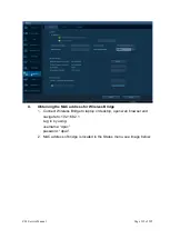
Overview of Procedure
Removal of Display Assy
Installation of Display Assy
Verification of LCD Display, Speakers, and Microphone
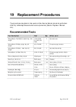
Required Tools/Equipment
9/32” Nut Driver or wrench
#1 Phillips Screwdriver
Removal Procedure
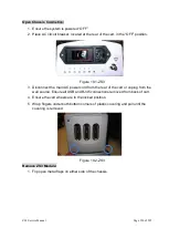
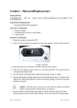
1. Ensure the system
is powered “OFF”.
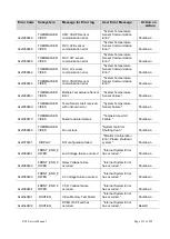
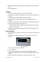
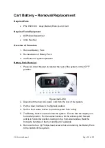
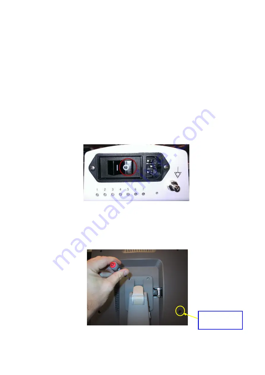
2. Place AC circuit breaker, located at the rear of the system
, in the “
0
” (OFF)
position.
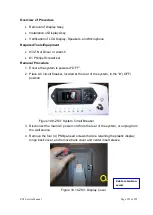
Figure 19.9-ZS3: System Circuit Breaker
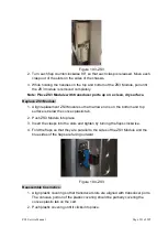
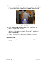
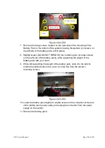
3. Disconnect the main AC power cord from the rear of the system, or unplug from
the wall source.
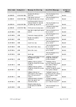
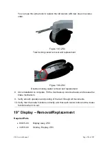
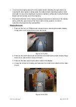
4. Remove the four (4) Phillips-head screws that are retaining the plastic display
hinge back cover, and remove back cover and center insert sleeve.
Figure 19.10-ZS3: Display Cover
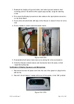
Cable retention
screw
Summary of Contents for Zonare ZS3
Page 1: ...ZS3 Diagnostic Ultrasound System Service Manual ...
Page 120: ...ZS3 Service Manual Page 120 of 295 FTP Setup Enters Setup Network FTP ...
Page 124: ...ZS3 Service Manual Page 124 of 295 ...
Page 131: ...ZS3 Service Manual Page 131 of 295 13 System Diagrams ...
Page 132: ...ZS3 Service Manual Page 132 of 295 Power Block Diagram Figure 13 1 ZS3 Power Block Diagram ...
Page 133: ...ZS3 Service Manual Page 133 of 295 Cabling Diagram Figure 13 2 ZS3 Cabling Diagram ...
Page 138: ...ZS3 Service Manual Page 138 of 295 Figure 14 6 ZS3 ...
Page 185: ...ZS3 Service Manual Page 185 of 295 17 Preventative Maintenance Forms ...
Page 217: ...ZS3 Service Manual Page 217 of 295 Figure 18 8 ZS3 ...
Page 252: ...ZS3 Service Manual Page 252 of 295 Figure 19 43 ZS3 Power Cable USB Cable ...
Page 295: ...P N 046 014026 00 2 0 ...


