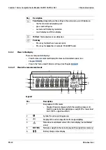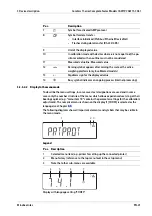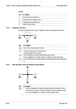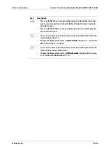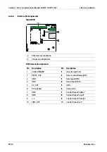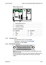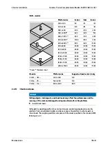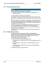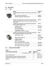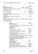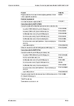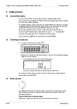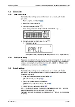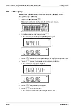
COM1 pin assignments
Pin
Description
Pin
Description
1
Shield
14
Internal ground (GND)
2
Data output (TxD)
15
Universal switch
3
Data input (RxD)
16
Control output "lighter"
4
GNO
17
Control output "equal"
5
Clear to Send (CTS)
18
Control output "heavier"
6
Not assigned
19
Control output "set"
7
Internal ground (GND)
20
Data Terminal Ready (DTR)
8
Internal ground (GND)
21
Ground power supply (GND)
9
Not assigned
22
Not assigned
10
Not assigned
23
Not assigned
11
+12 V for printer
24
Power 15 … 25 V (peripherals)
12
RES_OUT\
25
+5 V
13
+5 V Switch
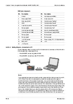
4.2.8.5.2 Cabling Diagram - Connection to a PC
Use the following cables to connect a PC to the indicator in accordance with the RS-232C/
V24 standard (max. cable length 15 m):
-
Model CAW1P: connecting cable 7357312
-
Model CAW1S: connecting cable YCC02-D9F6
RS-232
Note:
This equipment has been tested and found to comply with the limits pursuant to part 15
of FCC Rules. These limits are designed to provide reasonable protection against
harmful interference. This equipment generates, uses and can radiate radio frequency
energy and, if not installed and used in accordance with these instructions, may cause
harmful interference to radio communications. For information on the speciic limits and
class of this equipment, please refer to the Declaration of Conformity. Depending on the
particular class, you are either required or requested to correct the interference. If you
have a Class A digital device, you need to comply with the FCC statement as follows:
"Operation of this equipment in a residential area is likely to cause harmful interference
in which case the user will be required to correct the interference at his own expense."
Combics 1 Series Complete Scales Models CAW1P, CAW1S, CAS1
4 Device installation
EN-36
Minebea Intec

