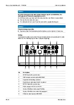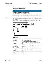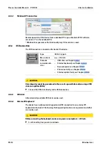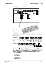
4.2 Control cabinet equipment
For PR 5900 with control cabinet and blackbox housing only.
Have all required parts, technical documents, and tools at hand for control cabinet
installation.
NOTICE
Ingress of dirt through the air vent in the housing.
There is a risk of damage being caused to the device.
Ensure that dirt does not enter the device when performing mechanical work on it
and/or in its vicinity.
Other procedure:
-
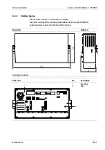
Make the drillings and control panel cut-out for the device in the control cabinet
door, for example; see Chapter
-
Install the device.
-
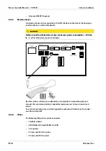
Secure the cable at the place of installation, e.g. using cable ties.
-
Remove the insulation from the cable ends and keep the strands short.
-
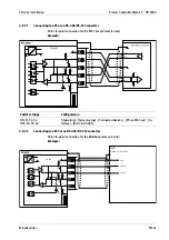
Connect the screens to the screen clamping rail using screen terminals; see
Chapter
-
Establish grounding/equipotential bonding between devices/system components
(this is essential for Ex applications); see Chapter
4.3 Table-top and wall devices
4.3.1
Cable gland and connection
The cables have to be fed into the device via glands to ensure leak-tightness. The
following cable diameters are suitable: 9…13 mm for gland M20×1.5 and 5…9 mm for
cable gland M16×1.5.
The cable wires are connected to the terminals inside the device.
The connections are made via plug-in terminals.
The conductors taken to the terminals shall be as short as possible. The wires of each
cable must be tied together with a cable strap shortly before the terminal.
4 Device installation
Process Controller Maxxis 5 PR 5900
Minebea Intec
EN-29
Summary of Contents for Maxxis 5
Page 137: ......


