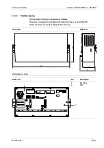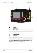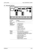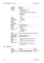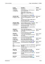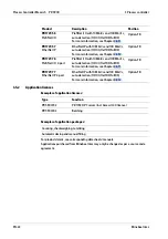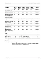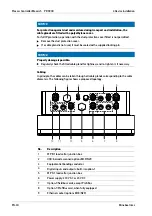
No.
Description
10
Option
‑
2
11
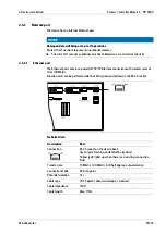
Internal serial interfaces/ProiBus card
12
Internal serial interfaces and option
‑
2
4.3.2
Installation of a cable
NOTICE
Material damage is possible.
Perform the connection of the cable screen for the ieldbus cards according to the
relevant chapter.
NOTICE
Material damage is possible.
Do not guide the screen (4) into the device!
The cable shield (4) must be connected in the metal sleeve (6) of the cable gland.
Before, during and after installation, make sure that the sealing ring is seated
correctly.
1. Unscrew the sleeve screw cap (1).
2. Slide the cap (1) and plastic cone (3) onto the cable (2).
3. Guide the cable (5) through the gland (6).
4. Fold the cable shield (4) over the lower part of the terminal insert (3) (approx. 10 mm).
5. Connect the cable conductors.
6. Tighten the sleeve screw cap (1).
7. Secure the gland (6) including the o-ring (7) using the counter nut (in the housing).
4 Device installation
Process Controller Maxxis 5 PR 5900
Minebea Intec
EN-31
Summary of Contents for Maxxis 5
Page 137: ......

