4. Device installation | 4.3 - Hardware construction | 51
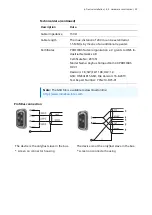
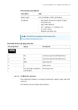
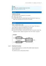
Allocation of the D-sub 9-pin plug connector
Pin assignment
Signal
Color
Description
Housing
S
Screen
1
not connected
2
not connected
3
RxD/TxD-P (positive)
according to
RS-485 specification
red
Send/receive data
Data core B/D (P)
4 if required
RTS
"Request To Send" (only when
using a repeater)
5
DGND
Insulated GND to RS-485 side
6
VP
Insulated power 5 V to
RS-485 side
7
not connected
8
RxD/TxD-N (negative)
according to
RS-485 specification
grün
Send/receive data
Data core A/D (N)
9
not connected
Note:
Only plug connections with integrated terminating resistors may be used.
The terminating resistor must be turned on in the last slave.


