7.5.5
Reading out calibration data for WP dead load and max using the front-panel keys
All settings for the device should normally be written down or printed out during
commissioning.
If an error occurs and a device must be replaced and no new calibration is carried out, the
values for the dead load and maximum load must be available in mV/V.
Procedure
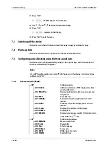
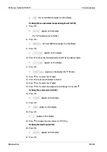
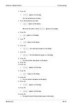
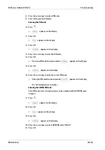
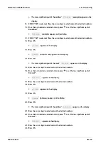
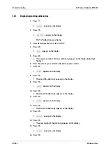
16. Press OK.
dEAdLo
appears on the display.
17. Press OK.
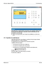
The mV/V value for the dead load appears on the display.
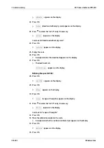
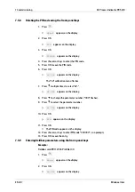
18. Press OK.
Cd 004
appears on the display.
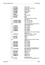
19. Press OK.
SPAn
appears on the display.
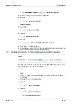
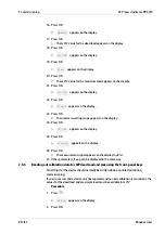
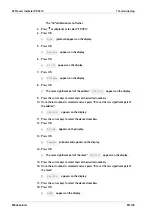
20. Press OK.
The mV/V value for the maximum load appears on the display.
21. Press OK.
Cd 005
appears on the display.
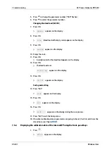
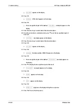
22. Press OK.
O-rnG
appears on the display.
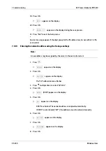
23. Press OK.
The used zero-setting range appears on the display.
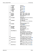
24. Press OK.
Cd 006
appears on the display.
25. Press OK.
uVoLt.d
appears on the display.
26. Press OK.
The measurement signal appears on the display in µV/d.
27. Other parameters, if any, can be displayed in the same way.
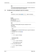
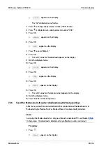
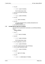
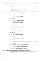
1.
Press
.
SEtuP
appears on the display.
2.
Press OK.
7 Commissioning
X3 Process Indicator PR 5410
EN-133
Minebea Intec

