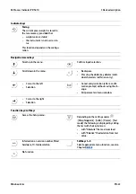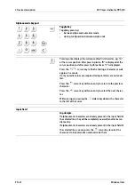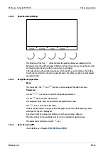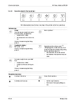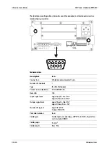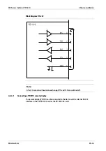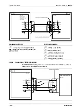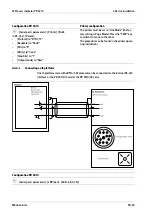
-
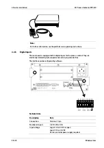
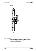
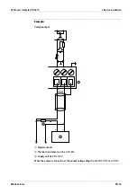
Remove the insulation from the cable ends and keep the strands short.
-
Connect the screens.
-
Establish grounding/equipotential bonding between devices/system components
(this is essential for Ex applications).
4.3
EMC-compliant installation
4.3.1
Connecting the screens
The screen for the D-Sub connector must be connected as described in Chapter
The screens for the connecting cable/load cell cable must be connected to the grounding
terminal on the back of the device.
4.3.2
Connecting the equipotential bonding conductor
The equipotential bonding conductor must be connected to the grounding terminal on
the back of the device.
4.4
Hardware construction
The main electronics is accommodated on the following units:
-
Main board
-
Display board
4.4.1
Main board
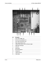
The main board provides the slots for the
-
Interface cards (accessories; see Chapter
)
-
Fieldbus card (accessories; see Chapter
The lithium battery (5, under the cover for the power supply) is always activated and
powers the calendar/clock module.
X3 Process Indicator PR 5410
4 Device installation
Minebea Intec
EN-32

