background image


10 


Output fluctuates 

abnormally. 

No

Inform Minebea about the contents 

of failure and situation in details 

Yes 

No

The connected tie-bar gage was 
broken or the signal path (signal 
conductor) might be 
disconnected. 

Approx. 5V is output. 

No

(1) Please confirm the condition of the connector 

for I/O. 

(2) Please confirm the operation of voltage output 

by check function. (Refer to paragraph 6.) 

Please remove the cable of tie-bar gage. 
Measure the resistance value between 1 pin and 4 pin 
of the connector for tie-bar gage side. 
(Please set the connection of the measuring 
instrument to ohm range.)   
Measure the resistance value between 7 pin and 2 pin 
of the connector for tie-bar gage side.   
Measure the resistance value between 4 pin and 5 pin 
of the connector for tie-bar gage side.   
Measure the resistance value between 2 pin and 3 pin 
of the connector for tie-bar gage side. 

Voltage is output. 

No

Yes 

Between 1 pin - 4 pin=350

Ω


Between 7 pin - 2 pin=350

Ω

Between 4 pin - 5 pin=0

Ω


Between 2 pin - 3 pin=0

Ω


Yes 

Inform Minebea about the contents of 
failure and situation in details 

Yes


Summary of Contents for CSA-593

Page 1: ...Transmitter for Tie bar gages CSA 593 Instruction Manual MINEBEA Co Ltd Measuring Components Business Unit 294 1511A ...

Page 2: ......

Page 3: ...escribed in this manual In this instruction manual the following marks are used to understand the matters that indicate Don t do this Caution and For reference Please be sure to read following descriptions for safety Warning This sign forewarns the presence of hazards that could result in serious injury or fatality when incorrectly handled Be sure to read to prevent from malfunction Caution This s...

Page 4: ... Places exposed to direct sunlight and or places in the high temperature Places in a highly humid area Places where the instrument is directly affected by vibrations or mechanical shocks Environments with full of dust or coarse particulates Environments containing of corrosive gas or salt Environments with raid change in temperature and or humidity Near the devices which generate magnetism or elec...

Page 5: ...the instrument and required dimensions for the environmental spaces are as follows I O signal side D SUB 9PIN Male 26 9 24 5 2 5 12 5 12 5 86 4 94 48 5 61 3 φ6 8 Fixed hole to CSA 593 Input side from tie bar gage D SUB 9PIN Female Unit mm Unit mm Shaded part Occupation area when main body is connected with connector plug ...

Page 6: ...instrument or an electric shock to an operator 3 Note for usage Caution When using the instrument check that wires are connected properly If neglected correct measurement cannot be obtained and it may cause malfunction in the instrument or cause damage to peripheral devices or a critical accident Caution Do not give the instrument such a shock as throwing something at it It may cause damage or des...

Page 7: ...V Revision history Date Ref No Contents Reason of revised 2012 08 DRW NO 294 1511 First version Ver 1 000 ...

Page 8: ...ING 3 3 4 CONNECTION OF POWER SUPPLY 4 4 MEASUREMENT 5 4 1 PREPARATION 5 4 2 EXECUTION OF AUTOMATIC ZERO 5 4 3 MEASUREMENT 5 5 AUTO ZERO A Z 6 5 1 SPECIFICATIONS 6 5 2 EQUIVALENT CIRCUIT OF THE EXTERNAL AUTO ZERO INPUT 6 5 3 FUNCTION 6 6 CHECK FUNCTION 7 6 1 SPECIFICATIONS 7 6 2 EQUIVALENT CIRCUIT OF EXTERNAL CHECK INPUT 7 6 3 FUNCTION 7 7 TROUBLE SHOOTING 8 7 1 EXECUTE TROUBLE SHOOTING 8 8 SPECIF...

Page 9: ...VIII 9 WARRANTY AND REAPIR 12 9 1 WARRANTY 12 9 2 REPAIR 12 ...

Page 10: ...VI ...

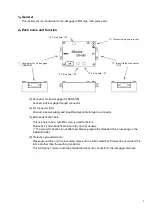
Page 11: ...ture Please fix by main body fixation hole A and C usually The screw for fixation is not attached Please prepare the threaded hole processing on the installatin side 6 Protective ground terminal Please ground this unit to prevent the noise such as static electricity Please do not connect this terminal other than the earthing conductor This terminal is common with the shielded terminal of a connect...

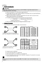
Page 12: ...s follows Connector for tie bar gage SENSOR Pin No Name 1 A 2 B 3 B 4 D 5 D 6 Shield 7 C 8 N C 9 Shield I O connector I O Pin No Name 1 24V 2 V OUT 3 V OUT 4 for adjustment 1 5 for adjustment 2 6 24V COM 7 A Z 8 CHECK 9 COM Suitable plug for I O connector Equivalent to DE 9SF N JAE Figure of a connector for tie bar gage seen from uniting side Socket side insert Figure of a I O connector seen from ...

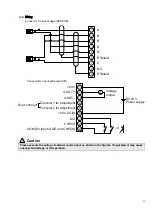
Page 13: ...ol input as shown in the figures If neglected it may cause unexpected damage or misoperation A E Shield N C C E Shield D D B B 7 8 2 3 4 5 6 1 9 1 2 3 4 5 6 7 8 9 24 V V OUT V OUT Terminal 1 for adjustment 24 V COM A Z CHECK COM for input of A Z and CHECK Terminal 2 for adjustment Don t connect or Voltage output DC24 V Power supply V ...

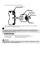
Page 14: ...or the I O connector cover and clamping the cable shield with metal fittings in the cover 3 4 Connection of power supply The power supply voltage and power consumption of CSA 593 is as follows Power supply voltage DC24 V Permissible variable range DC20 V 26 V Power consumption Within approx 50 mA at DC24 V Caution Please execute the connection of power supply surely and use within the specified po...

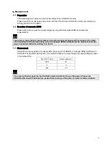
Page 15: ... be output in the initial strain condition at the first mounting on tie bar because ZERO calibration at the shipment of tie bar gage is executed without mounting it on tie bar 4 3 Measurement CSA 593 becomes possible to measure after the execution of ZERO set because SPAN calibration of CSA 593 is executed at the shipment The relation between the input range and output voltage is shown in the belo...

Page 16: ... 5 3 Function 1 The auto ZERO function works by shortening of circuit for about 50 ms or more between the external A Z and COM and the voltage output value becomes 0 zero after about 10 ms However the measurement of auto ZERO changes depending on the input condition turbulence etc Please confirm the timing at the change with a CSA 593 itself when the condition changes in the external control and m...

Page 17: ...e check function is used for maintenance 6 2 Equivalent circuit of external check input 6 3 Function The voltage output becomes DC 5 V while shortening the circuit between external CHECK COM regardless of the input condition from tie bar gage 2 2K 3300P 200Ω CHECK COM 5V ...

Page 18: ...ng CSA 593 Also please contact with Minebea when there is no corresponding item and when that abnormal operation is not improved even if the countermeasures are executed 7 1 Execute trouble shooting Operates normally Turn on the power again No Abnormal operation Yes Execute trouble shooting Start measurement Normal operation ...

Page 19: ... suitable for the specifications Yes Voltage output is wrong No Auto ZERO External control input does not work 1 No Yes The load resistance is 10 kΩ or more No Yes Wiring is correct No Please set the wiring correctly according to 3 3 Yes Within the range of auto ZERO operation No Please set the range within the auto ZERO operation Yes Yes Please set the load resistance 10kΩ or more ...

Page 20: ... the resistance value between 1 pin and 4 pin of the connector for tie bar gage side Please set the connection of the measuring instrument to ohm range Measure the resistance value between 7 pin and 2 pin of the connector for tie bar gage side Measure the resistance value between 4 pin and 5 pin of the connector for tie bar gage side Measure the resistance value between 2 pin and 3 pin of the conn...

Page 21: ... sampling rate 2 000 times s A D internal resolution 24 bit Output rate 2 000 times s Synchronous with A D sampling rate Output resolution Approx 1 10 000 Automatic ZERO range Approx 3 000 10 6 strain Required time for automatic ZERO Approx 60 ms Accuracy of automatic ZERO Within 5 mV Output for check Approx 5 V 8 2 General specifications 10 70 Operating temperature range 80 RH or less Non condens...

Page 22: ...urchased as for repairs and or after service is required during the period of warranty 9 2 Repair Before asking repairs please check once again that the connection the setting and the adjustment for the instrument have finished properly As a result of checking still there may have some defects in the instrument please contact with Minebea s sales office or sales agency from which you have purchase...

Page 23: ... ...

Page 24: ...un Nagano ken 389 0293 Japan 0267 32 2200 0267 31 1350 Measuring Components Business Unit FUJISAWA PLANT 1 1 1 Katase Fujisawa shi Kanagawa ken 251 8531 Japan 0466 22 7152 0466 22 1701 KARUIZAWA PLANT 4106 73 Miyota Miyota machi Kitasakugun Nagano ken 389 0293 Japan 0267 31 1309 0267 31 1350 HOMEPAGE ADDRESS http www minebea mcd com ...

Reviews: