KT60443-1G
䚷䚷
3-3. Mounting procedure
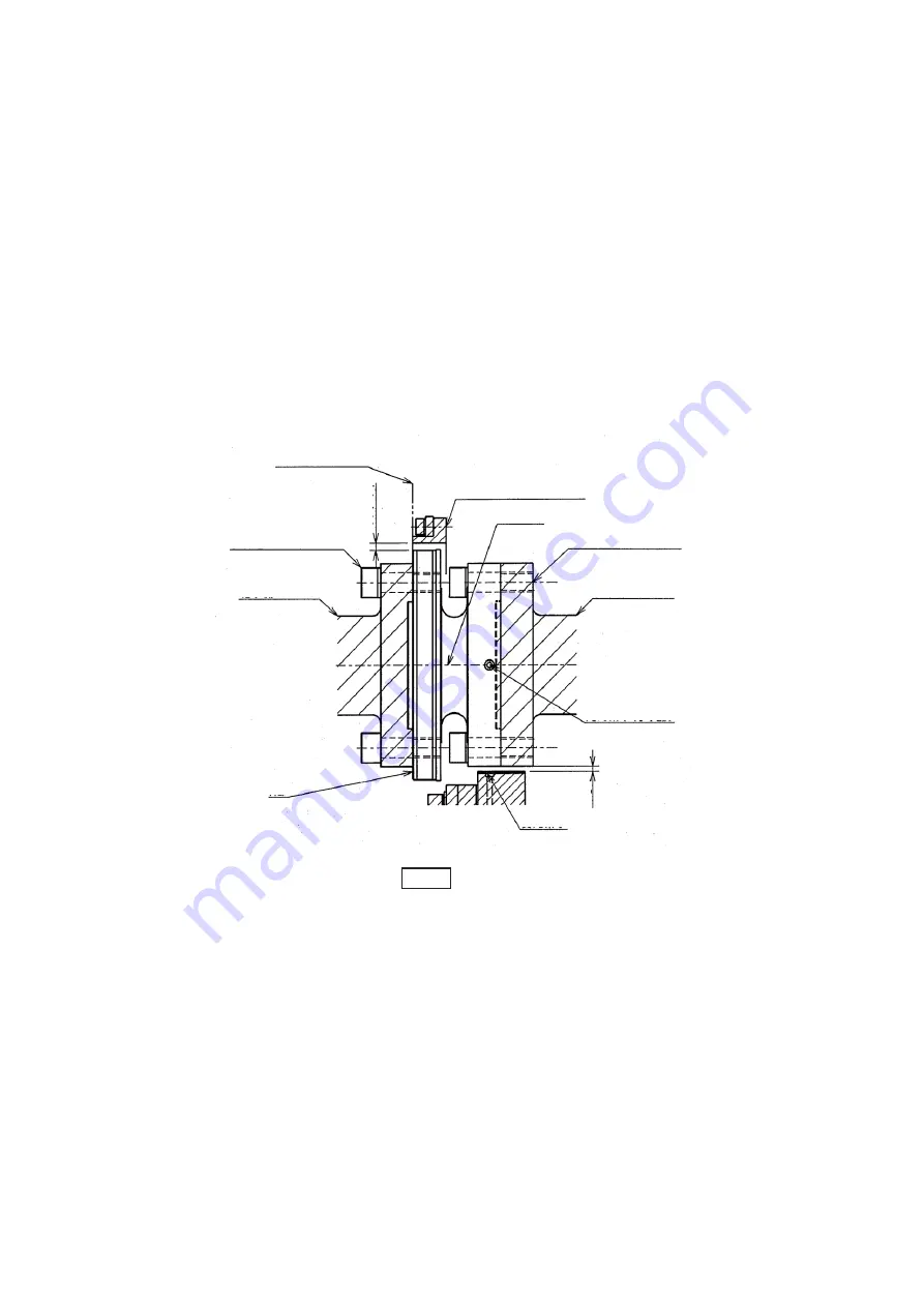
(1) Mount the rotor on the rotating shaft.
Before mounting the rotor, wipe off the rust inhibitor on the flange and spigot using
ethanol or other solvent. Make sure mounting surfaces are free of debris.
Clamp using M12 (M14 for 5KNM) hex socket head bolts.
Regarding the rotor spigot as a guide and to fix with M12
䠄
M14 for 5KNM) hex socket head bolts.
(See Fig. 1.)
For specific tightening torques, see the separate tightening torque table.
Tighten the eight evenly-spaced bolts by tightening opposite pairs uniformly,
first, to 1/4 of the tightening torque; then to 1/2 of the tightening torque; then finally
to the specified tightening torque.
Please be careful when mounting in case of the damage to the transmission coil(Bakelite bobbin)
on the rotor periphery.
After mounting, peel off the green tape protecting the photo emitter.
Fig. 1
(2) Separate the stator (antenna) and mount aligned with the rotor.
Remove the 6-M6 hex socket head bolts marked as "A" in Fig. 2.
Separate the antenna as shown in Fig. 2.
Be careful to avoid losing the bolts or flat spring washers attached when detaching.
Insert the rotor inside before reassembling the separated antenna.
Install by sliding the stator on the alignment face in Fig. 1 to ensure the correct shaft
orientation.
Align the stator so that it does not make contact with the rotor anywhere along its periphery.
The stipulated gap between the stator and rotor is 4 mm. This can be aligned visually.
Attach the stator using M8 bolts with plain and spring washers.
After securing the stator, fully tighten the bolts on the separated antenna.
Malfunctions may occur if the bolts on the antenna are not properly tightened.
M14 for 5KNM
M14 for 5KNM
Rotor/stator
alignment face
8-M12 socket head
bolts
Opposing flange
Section A
Stator (antenna)
Rotor
8-M12 socket head
bolts
Opposing flange
Photo emitter
(x8 evenly spaced)
Photoreceptor
G
ap 3
G
ap 4
MinebeaMitsumi Inc. Sensing Device Business Unit
4
Summary of Contents for TMOFB-3KNM
Page 8: ......


