background image

48

Version C

Mini-Cam 

Proteus Lite

WiFi Module

Your Proteus

 Lite system is enabled with a WiFi module to connect your CCU 

to a local company network, to allow an easy file transfer between the system 
and your office or local computer. It improves the speed of reporting without the 
need of exchanging SD cards or USB sticks.

Summary of Contents for Proteus Lite

Page 1: ...Original Instruction Manual Version C...

Page 2: ...2 Version C Mini Cam Proteus Lite...

Page 3: ...product Specifications dimensions and other statements in this document are subject to change without prior notice Mini Cam Ltd and its suppliers shall not be liable for any damages related to this so...

Page 4: ...C Declaration of Conformity 13 CE Declaration 13 System Overview 14 Warnings Safety Measures and Care 15 Before first use 17 Safety Measures 19 Maintenance 21 Cleaning 22 Checking Plug and Socket Conn...

Page 5: ...ower ON sequence 39 Power OFF sequence 39 Crawler function keys 40 Survey function keys 41 Camera function keys 43 Snapshot key 44 Recording and Playback keys 44 QWERTY keys 44 Pressurising Operation...

Page 6: ...intenance 66 CAM026 Pan Rotate Camera Module 67 Connections and Descriptions 68 Technical Details CAM026 68 Pressurising CAM026 69 CAM027 Axial Camera Module 70 Connections and Descriptions 71 Technic...

Page 7: ...List appears 86 The project is now opened 87 Using Project Sections 88 The list of Existing Sections is shown 88 If you chose to create a new section 89 The Sections List appears 89 The Section is now...

Page 8: ...Proteus Lite WEEE Statement 109 Information on Disposal for Business Users 109 In the European Union 109 For Spain 109 Countries outside the EU 109 Batteries 110 Product Serial Numbers 111 Useful Info...

Page 9: ...unit The warranty is a return to base warranty and we are not liable for any shipping costs Conditions of the Limited Warranty Disassembling the camera coiler control unit or any part of the system wi...

Page 10: ...a small inspection van or a low cost option for larger companies to use for off road remote locations Proteus Lite provides all the resources required to undertake efficient easy to perform inspectio...

Page 11: ...manual important information or guidance for system use Bold Font Bold font is used for important words For example This must not be done in reverse order Lists Lists are marked as follows item 1 item...

Page 12: ...ipes equal to and greater than 150mm diameter Different wheel sets and accessories allow the crawler to be centred in pipe sizes from 150mm to 1000mm The Auxiliary Light with Backeye Camera provides a...

Page 13: ...0 6 2 2005 Generic standards Immunity for industrial environments EN61000 6 4 2007 Generic standards Emission for industrial environments measurement control and laboratory use EHSR MSD Essential Heal...

Page 14: ...teus Lite System Overview The Proteus Lite inspection system consists of the following main components Control Unit A Cable Reel B Crawler C Camera D A typical configuration is shown in this illustrat...

Page 15: ...nt is used in a manner not specified by the manufacturer the protection provided by the equipment may be impaired DANGER Risk of deadly injuries from electrical current The mains plug and or IEC conne...

Page 16: ...on of the country in which this system is used DANGER Risk of deadly injuries from electrical current Although the cable reel and crawler could be used in wet environments the external PSU is for indo...

Page 17: ...Cam Service Centre Maintenance and repair work which is not covered in this document shall only be carried out by trained specialist staff at a Mini Cam Service Centre CAUTION Risk of serious injuries...

Page 18: ...losive substances such as gas or solvents If this kind of application should be required contact Mini Cam Ltd to obtain information on system components destined for this purpose CAUTION Suffocation h...

Page 19: ...zard conditions NOTE Safety of persons The staff for operation maintenance and upgrading must have specialist expertise or be instructed by competent individuals Competent individuals must have adequa...

Page 20: ...stem is responsible for the following aspects Only use the inspection system for work that is appropriate to the specifications Observe the operational requirements for this inspection system as descr...

Page 21: ...h a clean and dry cloth Keep all electrical connections and contacts free of dirt grease and moisture at all times bend the cable of the system and avoid knots Clean the cable with a rag when retracti...

Page 22: ...the system from the power supply General cleaning work CAUTION High pressure cleaners must not be used It can cause considerable damage to the crawler camera and other system components Cleaning agen...

Page 23: ...ck plate Check the contacts on the crawler camera connector with care Check the contacts on the crawler cable connector Check the contacts on the cable reel connector Check the contacts on the control...

Page 24: ...to the crawler axle C 3 Turn the wheel retainer bolt clockwise to lock the wheel onto the axle NOTE To remove the wheel turn the retainers bolt anti clockwise ensure that the retainer is aligned with...

Page 25: ...reel as illustrated 1 Plug the male plug A of the link cable into the back of the control unit B Notice the orientation of the plugs Secure in place with locking ring C 2 Plug the female plug D of th...

Page 26: ...back of the crawler as illustrated 1 Plug the cable end connector A into the crawler connector D Notice the orientation of the socket C 2 Turn the retaining ring B clockwise as viewed from the cable t...

Page 27: ...l cable from the back of the crawler as illustrated 1 To unscrew the retaining ring you must pull the ring away from the crawler body before rotating anti clockwise NOTE Always fit the protective caps...

Page 28: ...anual quick release elevator to enable adjustment of the camera height position 1 Use a 4mm Allen Key A to loosen the two hex bolts B 2 Grip the elevator arm C firmly and pull upwards to the required...

Page 29: ...e locking ring A is rotated fully clockwise as viewed in the diagram with the locking hole B in the 12 o clock position 3 Notice the orientation of the locking pin C on the rear of the camera Fit the...

Page 30: ...Lite Protective Cap NOTE Always fit the protective caps when the camera is not in use to protect from damage ingress of dirt and moisture Proteus CPL150 Crawler with CAM026 Pan Rotate Camera attached...

Page 31: ...OFF Connect the auxiliary module ALB300 to the crawler as illustrated 1 Remove the protective cap screws A 2 Remove protective cap B 3 Fit the auxiliary module C to crawler Notice the orientation as...

Page 32: ...before the inspection begins NOTE The internal pressure of each pressurised module may vary Refer to the specific module technical specification for correct pressure information The control unit disp...

Page 33: ...ressure regulator for the CO2 or Nitrogen to 10 PSI 4 Ensure the crawler pressure is within the acceptable range by checking the pressure gauge on the control unit An example is shown below Refer to t...

Page 34: ...directly at the camera or auxiliary module illumination When checking the illumination use a low power setting and view from an angle greater than 50 from the centre of the module Check the following...

Page 35: ...ler by means of the crawler cable D so that it does not contact the chamber Carefully lower the crawler into the invert of the chamber 3 Detach the hook B from the crawler lowering handle C NOTE To re...

Page 36: ...card Sunlight viewable display 1024x768 pixels Video recording in MPEG 4 AVC H 264 formats Pictures saved in JPG format Customisable colour on screen text overlay Video output of live video with on s...

Page 37: ...4 x 768 pixels 2 Left joystick for crawler control 3 Right joystick for camera control 4 Speaker 5 ON OFF button 6 ALL STOP button 7 Crawler function keys 8 Survey Function keys 9 Media function keys...

Page 38: ...e power to the crawler When power to the crawler is disabled a red light next to this button is illuminated When the control unit is powered ON this key must be pressed to enable power to the crawler...

Page 39: ...control unit will sound an audible beep several times and the red light next to the ALL STOP button will be illuminated If this should happen first check all connections on the system are made correct...

Page 40: ...se until maximum speed is reached b When the crawler is travelling forward each press slows the crawler speed 4 Crawler settings a Select the correct wheel size attached to the crawler for accurate sp...

Page 41: ...C Mini Cam Proteus Lite 1 3 2 Survey function keys 1 Meterage a Change meterage manually b Change position of meterage on the screen 2 Text a Change text colour 3 Survey Folder a Start ProPIPE or Win...

Page 42: ...C Mini Cam Proteus Lite Media function keys 1 Copy a Copy files from one media source to another 2 Storage media a Choose storage media Internal USB SD card 3 Gallery a Browse surveys videos and pict...

Page 43: ...ersion C Mini Cam Proteus Lite Camera function keys 1Digital Zoom 2 Camera Illumination 3 Focus 4 Focus 5 Camera Home a Automatically move camera to home position CAM026 only 6 Camera Settings 6 1 4 3...

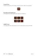
Page 44: ...s this key to take a JPG image of the live video or video during playback Recording and Playback keys These keys control the recording and playback of video files QWERTY keys These keys allow the user...

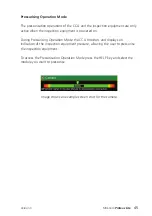
Page 45: ...ection equipment is powered on During Pressurising Operation Mode the CCU monitors and displays an indication of the inspection equipment pressure allowing the user to pressurise the inspection equipm...

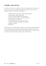
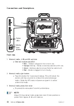
Page 46: ...o remove from the control unit Red Media is plugged in but is faulty 2 External media eject button a Press this button for 1 second and release This will instruct the control unit that you wish to unm...

Page 47: ...for the crawler and charges the control unit internal battery 2 Connection to Cable Reel 3 Expansion Slot Protection Cover a To protect the expansion slot from ingress of dirt and moisture NOTE Always...

Page 48: ...ite system is enabled with a WiFi module to connect your CCU to a local company network to allow an easy file transfer between the system and your office or local computer It improves the speed of rep...

Page 49: ...This feature allows the user to connect the CCU to WiFi 1 Select WiFi from the Setup and Configuration drop down menu 2 A menu will be displayed giving options to connect to WiFi 3 Select Stored F3 Ye...

Page 50: ...Lite 4 Select Find WiFi F1 Red Key to search for available networks 5 Select the required network from the menu 6 Select Connect F1 Red Key to connect to the selected network you will have to type a...

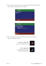
Page 51: ...ess followed by connection confirmation signal strength and IP Address 8 The main display screen shows the WiFi status icon at the bottom right hand side of the sidebar WiFi NOT CONNECTED Red cross in...

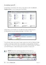
Page 52: ...r Proteus Example 192 168 1 144 This will then connect you to your Proteus control unit which will display a folder named CCU Memory Double click on this folder to access all files currently on that c...

Page 53: ...sending process A message will be displayed with the sending progress which will display Sent when the email has been dispatched NOTE The most recent Address CC Address and Subject are stored over th...

Page 54: ...ing file sharing The share icon will be visible in the right bottom corner until the Email or WincanWeb has finished sending The progress can be also seen in the Share Status which can be accessed aft...

Page 55: ...eaners must not be used It can cause considerable damage to the control unit crawler camera and other system components Cleaning agents or solvents must not be used These can damage the seals and othe...

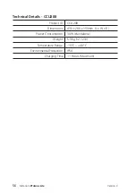
Page 56: ...Lite Technical Details CCU208 Product ID CCU208 Dimensions 430 x 280 x 150mm L x W x D Power Consumption 30W standalone Weight 5 5Kg 12 12lb Temperature Range 10 C 40 C Environmental Protection IP54 C...

Page 57: ...le unit which houses the cable reel and CCU It has the following features Unique cow horn locators for easy fitting of the CCU Meterage Roller 250m Kevlar reinforced cable Friction brake Fold away Rem...

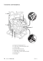
Page 58: ...ctions and Descriptions A Cow horn locators for CCU B Cable layering arm Meterage wheel C Friction brake D Spring loaded connector E Fold away winding handle F 250m 6 8mm Kevlar reinforced cable G Int...

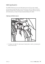
Page 59: ...ed tangle free pay out and rewinding of the 250 metres of 6 8mm Kevlar reinforced cable The layering arm is designed to open easily for cleaning and maintenance a simple two step procedure releases th...

Page 60: ...Lite 2 Grip the lower arm B firmly and use the knob C on the top arm to raise the arm and open the assembly 3 To release the assembly D from the meter counter bar E squeeze the spring clips F while l...

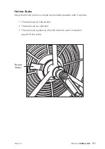
Page 61: ...ion Brake Using the friction brake is a simple one handed operation with 3 options 1 The brake can be fully locked 2 The brake can be unlocked 3 The brake can applied as a friction brake to avoid unwa...

Page 62: ...g Handle The winding handle is used for paying off and rewinding the cable For safe storage and space saving the grip handle can be folded inside the arm For cleaning and maintenance the complete hand...

Page 63: ...moisture and fit the protective cap Maintenance Ensure that all screw threads and connections are free from dirt CAUTION High pressure cleaners must not be used It can cause considerable damage to the...

Page 64: ...Multi frequency sonde location transmitter Optional Inclination sensor for constant monitoring of the pitch Optional Performance wheels for specific conditions Optional CPL150 is pressure tight up to...

Page 65: ...andle B Hex bolts to elevator release C Manual elevator D Camera housing E Auxiliary light connection protector F Pressurisation point G Camera CAM026 H Connector for camera J Crawler wheel K Quick Re...

Page 66: ...tem Crawler wheels For inspection in various pipe systems always use the appropriate wheel combinations Maintenance Ensure that all screw threads and connections are free from dirt CAUTION High pressu...

Page 67: ...It has the following features High resolution colour CCD image sensor Powerful LED lighting with narrow beam width lenses Endless rotation range Panning range of 135 Motorised focus control Internal p...

Page 68: ...lens E Rubber protector F Rubber protector G Pressure valve protection cap H Camera protection skid J Camera protection skid screws x6 Technical Details CAM026 Product ID CAM026 Dimensions 120 x 73 x...

Page 69: ...the pressure valve connection adaptor A 3 Set the pressure regulator for the CO2 or Nitrogen to 5 PSI 4 Ensure the crawler pressure is within the acceptable range by checking the pressure gauge on th...

Page 70: ...esolution colour axial camera for the Proteus Lite inspection system It has the following features High resolution colour CCD image sensor Powerful LED lighting with narrow beam width lenses Motorised...

Page 71: ...onnector 2 LED illumination 3 Camera lens 4 Serial number location Technical Details CAM027 Product ID CAM027 Dimensions 63 x 52 x 52mm L x W x H Power Consumption 7W Weight 0 25Kg 0 55lb Temperature...

Page 72: ...on for the forward view camera and a rear view high resolution colour camera for the PROTEUS platform It has the following features High resolution colour CCD image sensor Powerful LED lighting with n...

Page 73: ...84 x 68 x 50mm L x W x H Power Consumption 4W Weight 0 32Kg 0 70lb Temperature Range 20 C 50 C Environmental Protection Pressurise Tested IP68 Internal Pressure None Connections and Descriptions 1 For...

Page 74: ...from dirt and moisture Always fit the protective cap immediately after disconnecting the camera module from the system Maintenance Ensure that all screw threads and connections are free from dirt Repl...

Page 75: ...Mini Cam SOLOPro WinCan Embedded and ProPIPE Reporting Software for Proteus and SOLOPro Systems Version A 75 Version C...

Page 76: ...s and their videos photos and report documents You can n Have as many Projects as you want n Add Sections to Projects whenever you want n Create close save reopen and edit previously created Projects...

Page 77: ...our Project type n Create a New Project or open an Existing Project n Create a New Section in that Project or open an existing Section n Perform the Survey first filling in the Header Information then...

Page 78: ...s a Detailed User Guide containing screenshots and more information Create a New Project n Press then choose or n Press to create a New Project n Use and to select the survey standard n Enter the Proj...

Page 79: ...for you to enter the Section Header details Enter the Section Header Information n Enter all relevant Section Header information Anything marked with a is required information which needs to be enter...

Page 80: ...press the Record key when you want to begin Press now and this information box will disappear n The screen will now display a live picture with your chosen Header Information showing on screen Start Y...

Page 81: ...ght the relevant Defect Code and press Once you have entered or selected your Defect Code you fill in the information it asks for Then press to store the New Observation with no photo or press to stor...

Page 82: ...y press then in the control menu that appears select End Survey and press You will be prompted to Confirm End Survey by pressing n A summary of the Section which has just been completed is then shown...

Page 83: ...hoose the style of report that you want The report is saved into the Project s folder along with the video and photos You can copy the report onto a USB memory device using the Gallery Browser for lat...

Page 84: ...l the information about that Project s Sections and their videos photos and report documents Press the Projects key and the Project Type choice appears n Choose or The Projects List appears n If you h...

Page 85: ...reate a New Project press Or to open an existing Project highlight it using the arrows and then press If you chose to create a New Project n Use the arrows to select which Inspection Standard you wish...

Page 86: ...nts for the Project of you wish n Press to create the Project The Projects List appears n If you just created a New Project it will appear in this list n Choose a Project to open n Highlight the Proje...

Page 87: ...is now opened n A summary of the Project is shown n A New Project will not yet have any Sections n An existing Project may already have Sections Press to see existing Sections or create New Sections...

Page 88: ...n If the Project has any existing Sections they will appear in the list n If the Project has no existing Sections the list will be empty You can choose to create a New Section in the Project or open a...

Page 89: ...ction n You may also enter comments for the Section of you wish n Press to create the Section The Sections List appears n If you just created a New Section it will appear in this list n Choose a Secti...

Page 90: ...e Observations If this is an Existing Section it may already have had a survey performed for it and will have existing Observations n Press to review the existing Observations for this Section You can...

Page 91: ...ou chose to perform a survey for the Section The Survey Header Information appears n Type in or select the appropriate information for the survey n Anything marked with a is mandatory information that...

Page 92: ...throughout the whole survey Press the key and the choices of the coloured keys change n Press to toggle whether the Header Item is shown briefly at the start of the survey n Press to toggle whether t...

Page 93: ...Cam SOLOPro After entering all the Header Information you can enter some comments for the Survey n Type in some Survey Comments if you wish n Then press to prepare for performing the survey 93 Versio...

Page 94: ...SOLOPro The system is now in Survey Standby waiting for you to begin the survey n Video recording is ready but is paused n Press the key and position the inspection equipment ready for the survey 94 V...

Page 95: ...ing press the Record key n Video recording starts n Your selected On Video Header Information text about the survey appears on the camera screen and is recorded onto video n After a short time this in...

Page 96: ...When you see a Defect you can create an Observation for it Press the Projects key and the Survey Features menu appears n If you know the Defect Code you can simply type it in n If you don t know the c...

Page 97: ...e to Lookup the Defect Code You see a list of the Defect Code categories n Use the arrows and to browse the Defect Code categories to find the Defect Code that you require n When you have found the De...

Page 98: ...r the Observation n Anything marked with a is mandatory information that must be provided n There may be more than one page of Observation Information n When you have entered the information you can s...

Page 99: ...ervation Text information is shown on the camera screen n The system takes a photo with this information on it n After a short time the information is removed Video recording then restarts automatical...

Page 100: ...Survey Press the Projects key and the Survey Features menu appears n Select End Survey and press You are asked to confirm you do want to end the survey n Press to confirm n Any other key cancels endi...

Page 101: ...viewing the Survey Viewing the Observations When you have selected a Section the Section Information is shown n Press to Review the existing Observations for this Section The Section Observations are...

Page 102: ...ess if you want to Delete the Observation you will be asked to confirm the delete You can also create a New Observation if one was missed when the Survey was being performed n Press to create a New Ob...

Page 103: ...tion n This is done in the same way as when the Survey was originally performed n Either enter the Defect Code directly or use Search or use the Lookup When you have selected the Defect Code for the n...

Page 104: ...List of Observations n New created Observations don t have photos n The Observations are sorted into ascending distance order Creating Reports Creating Reports for the Whole Project When you have sel...

Page 105: ...reviews of the various Report Styles are displayed n Press the relevant coloured key to generate a report document of your chosen style n Most reports are generated as both RTF and PDF documents n The...

Page 106: ...Section Information is shown n Press to generate Report Documents of this Section Previews of the various Report Styles are displayed n Press the relevant coloured key to generate a report document o...

Page 107: ...Mini Cam SOLOPro n The style generates only RTF n The report documents are stored into the Project s memory Folder along with the Project s video and photo files 107 Version C...

Page 108: ...108 Version C Mini Cam Proteus Lite...

Page 109: ...SOLOPro CCU is marked with the symbol shown above It means that used electrical and electronic products should not be disposed of in with general household waste Contact your Local Council who will ad...

Page 110: ...and recycling We are required to do this in any calendar year we place new industrial batteries on the market If any of our customers or in certain cases other end users require us to take back indust...

Page 111: ...tion UK Customers For service and repair contact Mini Cam Ltd Tel 44 0 1942 444555 Email service minicam co uk International Customers For service and repair contact your local Mini Cam Approved Deale...

Page 112: ...112 Version C Mini Cam Proteus Lite...

Page 113: ...113 Version C Mini Cam Proteus Lite Notes...

Page 114: ...114 Version C Mini Cam Proteus Lite Notes...

Page 115: ......

Page 116: ...Mini Cam Ltd WinCan is a trademark of CD Lab AG Specifications subject to change without notice Mini Cam Ltd is a Halma Company Mini Cam Limited Unit 4 Yew Tree Way Stonecross Park Golborne Warringto...

Reviews: