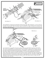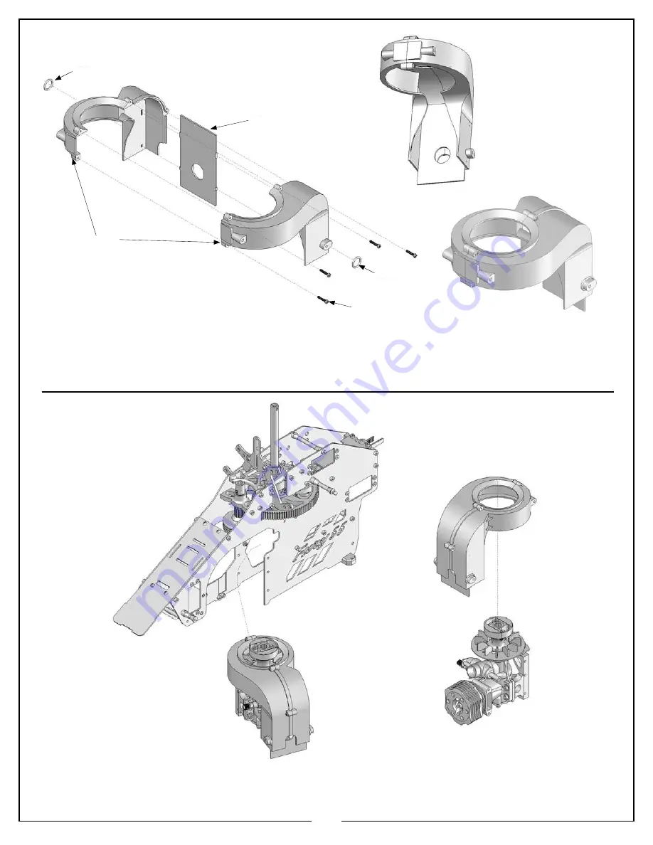
Locate the MA128-123 fan shroud set, the MA128-125 shroud deflector, two MA128-128 rubber “o” rings, and four MA0029 m2x2x13
Phillips self tapping screws. Refer to
Illustration 2d.1, 2d.2
and
2d.3
for this step. Bring the two sides of the MA128-123 fan shroud
set together with the MA128-125 shroud deflector between them. If there is flashing on the MA128-123 fan shroud, it can be easily
trimmed with a razor knife. Note the correct orientation of these parts in the illustration. Use the four MA0029 m2.2x13 self tapping
Phillips screws to join the fan shroud set together. Stretch the two MA128-128 rubber “o” rings over the alignment tabs as shown.
Place the completed fan shroud assembly onto the completed engine assembly. This will install from the left side of the main frame
assembly. Refer to
Illustration 2e
.
20
Illustration 2d.1
Illustration 2e
Illustration 2d.2
Illustration 2d.3
128-128
128-125
128-123
128-128
0029
4x
Summary of Contents for Fury 55 X-CELL
Page 1: ...Assembly instructions Step up to Excellence with X cell...
Page 2: ...2...
Page 30: ...30 Bag 5 Hardware...
Page 43: ...43 Completed Airframe with Electronics Engine and Muffler Installed...
Page 51: ...51 Notes...
Page 52: ...52 Notes...
Page 53: ...53 Notes...
Page 54: ...54 Notes...

