27
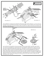
Locate the two MA128-148 boom support assemblies, MA128-149A upper boom support clamp, and MA128-149B lower boom support
clamp, MA128-59 front boom support spacer, two MA0065 m3x12 socket bolts, four MA0064-9 m4x10 button head socket bolts, and four
MA0016-1 external serrated lock washers. Refer to
Illustration 3-4e
for this step. Install the MA128-148 boom support assemblies to the
main frame assembly (notice that the aluminum boom support ends have a dimple on one side. The dimple indicates a slight angle built
in to this part. On the boom support assembly side that attaches to the main frame, the dimple will be facing “in”) using two MA0064-9
m4x10 socket bolts, and two MA0016-1 external serrated lock washers per side. For added security of this part, we recommend using a
“green” retaining compound such as MA3200-22 “super lock-green” on the MA0064-9 m4x10 socket bolts. Install the MA128-149 (A
and B) onto the tail boom, and attach the boom support assemblies using two MA0064-9 m4x10 button head bolts, and two MA0016-1
external serrated lock washers per side. Take care to not overtighten the MA0065 m3x12 socket bolts, doing so may result in crushing the
tail boom. Again, the use of “green” retaining compound is recommended on the MA0064-9 m4x10 button head bolts.
Locate the MA128-159 T/R pitch slider assembly, two MA0361 control balls, two MA0159 ball bearings, MA0445 plastic T/R bell
crank, MA0579-3 brass spacer, two MA0049-3 m2x8 socket bolts, and one MA0017 hex nut. Refer to
Illustration 3-4f
for this step.
Install an MA0361 control ball using an MA0049-3 m2x8 socket bolt into the middle hole of the MA0445 plastic T/R bell crank. It
is recommended that you use a drop of CA (cyanoacrylate) on the threads of the MA0049-3 m2x8 socket bolt before threading the
bolt into the plastic of the MA0445 plastic T/R bell crank. Insert an MA0159 ball bearing followed by the MA0579-3 brass spacer,
and then the second MA0159 ball bearing. Install the bell crank to the aluminum bell crank mount using the MA0091 Phillips bolt.
After the MA0091 Phillips bolt threads through the aluminum bell crank mount, use the MA0017 hex nut on the exposed threads of
the bolt. Install an MA0361 control ball using a MA0049-3 socket bolt into the pitch slider assembly. It is recommended that you
use a drop of CA (cyanoacrylate) on the threads of the MA0049-3 m2x8 socket bolt before threading the bolt into the plastic. Slide
the MA128-159 pitch slider assembly onto the tail rotor shaft as shown in the illustration.
Apply a small amount of
medium thread lock when
threading into metal parts
High-Strength
Thread Lock
High-Strength
Thread Lock
High-Strength
Thread Lock
High-Strength
Thread Lock
CA
CA
Illustration 3-4e
Illustration 3-4f
Thread
Lock
0064-9
0016-1
129-149-A
129-149-B
0016-1
0064-9
129-148
129-59
0016-1
0064-9
0016-1
0064-9
0065
2x
128-159
0361
0049-3
0159
0445
0017
0579-3
0159
0091
0361
0049-3
Summary of Contents for Fury 55 X-CELL
Page 1: ...Assembly instructions Step up to Excellence with X cell...
Page 2: ...2...
Page 30: ...30 Bag 5 Hardware...
Page 43: ...43 Completed Airframe with Electronics Engine and Muffler Installed...
Page 51: ...51 Notes...
Page 52: ...52 Notes...
Page 53: ...53 Notes...
Page 54: ...54 Notes...


