background image

32

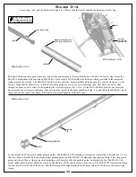
Locate the MA128-172 G-10 servo retainers, the carbon fiber cyclic servo spacers, eight MA0039-2 m2.5x16 Phillips bolts, and two 

of the servos you have chosen for cyclic control of the swashplate.  Please refer to 

Illustration 5c

 for this step. Miniature Aircraft USA 

realizes that there are many different brands and models of servos available, and many have slightly different servo arm heights.  We 

have included the spacers required for proper alignment of the control rod for nearly any servo available.  Using the MA0039-2 m2.5x16 

Phillips bolts and MA128-172 G-10 spacers OR MA128-173 carbon fiber spacers mount the left and right cyclic servos as shown in the 

illustration.  Do not mount the servo arms to the servos at this time.  There already are PEM nuts pressed into the cyclic servo mounts for 

this purpose. NOTE: you may have to change the servos spacers in a later step to insure proper alignment of the control rod.

Locate two MA128-170 plastic servo blocks, the MA128-172 G-10 servo retainers, four MA0039-2 m2.5x16 Phillips bolts, and 

one more cyclic servo. Refer to

 Illustration 5d

 for this step. Using the MA128-170 plastic servo blocks, the MA128-172 G-10 servo 

retainers and the MA0039-2 m2.5x16 Phillips bolts, mount the servo into the frame as shown in the illustration.  There already are 

PEM nuts pressed into the frame for this purpose.  NOTE: you may have to change the servos spacers in a later step to insure proper 

alignment of the control rod.

Apply a small amount of 

medium thread lock when 

threading into metal parts

Illustration 5c

Illustration 5d

0039-2

4=SERvo

128-172

SERvo

128-172

oR 128-173

SEE noTATIon In

WRITTEn TExT

ELEvAToR SERvo

128-172

2x

128-170

2x

0039-2

4x

gyRo LoCATIon

Summary of Contents for Fury 55 X-CELL

Page 1: ...Assembly instructions Step up to Excellence with X cell...

Page 2: ...2...

Page 3: ...ts List 17 Bag 2 Assembly Instructions 18 Bag 2 Completed Assembly Diagram 23 Bag 3 4 Assembly 24 Bag 3 4 Hardware 24 Bag 3 4 Pre Assembled Parts List 24 Bag 3 4 Assembly Instructions 25 Bag 3 4 Compl...

Page 4: ...ght have been developed by experienced flyers and are set down here It is urged that they be read understood and followed Warning Risk of death or serious injury Remote Control R C Helicopters can be...

Page 5: ...del airplane competition AMA is the chartering organization for more than 2 500 model airplane clubs across the country AMA offers its chartered clubs official contest sanction insurance and assistanc...

Page 6: ...p Tool MA3000 02 6 Optical Heli Tachometer MA3000 50 Other required components The X Cell Fury 55 is an airframe kit To complete the model several other items are required but are not included with th...

Page 7: ...tten in such a way that each step builds upon the work done in the previous step Changing the order of assembly may result in unnecessary steps Clean all metal parts All of the steel parts in this kit...

Page 8: ...5 C F Shroud Deflector 062 1 2 B 128 128 1 2 x 3 8 x 1 16 Rubber O Rings 2 2 B 128 22 C F Rear Fan Shroud Mount 062 1 2 B 128 28 C F Left Front Frame Plate 062 1 2 B 128 65 Landing Gear Mounting Block...

Page 9: ...ent Gauge 1 5 B 128 170 Plastic Servo Blocks 2 5 B 128 172 G 10 Servo Retainers 1 5 B 128 173 090 Carbon Cyclic Servo Spacers 1 5 B 3200 46 1 2 x 20 hook and loop tape 1 5 B 3200 48 3 4 x 15 hook and...

Page 10: ...arts Pre Assembled from Factory Lower Main Shaft Bearing Block Upper Main Shaft Bearing Block Aluminum Idler Pulleys Autorotation Hub 128 40 128 55 128 70 128 49 0183 0183 128 55 128 71 122 28 128 71...

Page 11: ...in this step Using the MA0060 1 m3x6 socket bolts attach the MA128 55 upper main shaft bearing block but do not fully tighten the bolts at this time Using two MA0061 m3x8 socket bolts attach the MA128...

Page 12: ...a PEM nut in the frame Locate the MA128 67 aluminum pulley mount two MA128 70 aluminum idler pulley s note that the bearings have been installed at the factory two MA0067 m3x14 socket bolts two MA128...

Page 13: ...x6 socket bolt and one MA0061 m3x8 socket bolt into the lower bearing block as show Note that the bolts threading into the upper and lower bearing blocks should not have been fully tightened at this t...

Page 14: ...to Illustration 1h for this step Attach the MA128 16 anti rotation guide to the front of the servo mounts using the MA0064 3 m3x6 button head socket bolts There is a PEM nut installed into the servo m...

Page 15: ...he MA128 49 autorotation hub Tighten the MA0019 m3 locknuts equally around the hub Do not use thread locking compound on lock nuts Loosely thread the MA0059 1 m2 5x6 socket bolt into the MA0875 main s...

Page 16: ...MA128 46 tail rotor drive pulley The MA0058 5 m5x8 dog point set screw will thread into the pulley and extend into the indention on the main shaft The MA0058 6 m5x5 socket set screw will simply tighte...

Page 17: ...rts Pre Assembled from Factory 17 Clutch Bell Unit Start Shaft Assembly Centrifugal Clutch Clutch Drive Bearing Block 128 40 128 121 105 70 0208 128 106 128 109 128 110 128 114 128 112 0283 0439 128 1...

Page 18: ...d line up the flat spot with the threaded hole on the hex start adaptor Thread the MA0057 m4x4 set screw into the hex start adaptor taking care not to allow vertical play in the start shaft assembly L...

Page 19: ...own there will be no crankshaft play It is CRITICAL that this nut is not cranked down at this point as the fan hub will become distorted Thread the two MA0063 m3x10 socket bolts into the aluminum fan...

Page 20: ...hroud it can be easily trimmed with a razor knife Note the correct orientation of these parts in the illustration Use the four MA0029 m2 2x13 self tapping Phillips screws to join the fan shroud set to...

Page 21: ...MA128 65 landing gear mounting block to the MA128 28 left front frame plate Use one MA0061 m3x8 socket bolt and one MA0060 1 m3x6 socket bolt to attach the MA128 22 rear fan shroud mount to the left m...

Page 22: ...e seal between the rubber fuel tank plug and the tank With the remaining piece of fuel line we have found that a 190mm piece works from the tank vent to the muffler pressure nipple and a 140mm piece w...

Page 23: ...g gear mounting blocks Slide the two MA128 66 aluminum skids through the struts and position them as desired Thread the MA0058 1 m4x6 socket set screws into the strut and gently tighten just enough to...

Page 24: ...Rotor Pitch Slider Assembly Tail Rotor Idler Boom Support Assembly Tail Plate Assembly 128 159 0442 2x 0225 2x 0443 0440 128 160 0439 0437 0439 0435 0159 0159 128 157 128 145 128 146 0058 3 128 148 O...

Page 25: ...alignment of the tail boom Locate three MA128 144 plastic rudder pushrod guides and the MA128 155 aluminum transmission clamp Refer to Illustration 3 4c for this step Locate three MA128 144 plastic r...

Page 26: ...x5 dog point set screw into the pulley making sure that the dog point of the set screw is engaged into the dimple Thread in the MA0053 m3x5 socket set screw into the other hole on the pulley There is...

Page 27: ...59 ball bearings MA0445 plastic T R bell crank MA0579 3 brass spacer two MA0049 3 m2x8 socket bolts and one MA0017 hex nut Refer to Illustration 3 4f for this step Install an MA0361 control ball using...

Page 28: ...pound such as MA3200 22 super lock green applied to threads of the MA0021 m4 lock nut The best way to apply this compound is with a very small amount on the tip of a toothpick It is very important to...

Page 29: ...the T R control rod guides Make sure they are aligned so that there are no bends in the T R control rod Thread on the other MA0133 ball link It is important to align the T R control rod guides so tha...

Page 30: ...30 Bag 5 Hardware...

Page 31: ...ntrol ball and thread the MA0109 m3x8 threaded control balls into each washout arm Press an MA128 176 washout pivot pin into the MA0869 plastic washout link through the MA0221 plastic washout arm This...

Page 32: ...EM nuts pressed into the cyclic servo mounts for this purpose NOTE you may have to change the servos spacers in a later step to insure proper alignment of the control rod Locate two MA128 170 plastic...

Page 33: ...using the four MA0038 m2 5x10 Phillips bolts Thread the two MA0133 plastic ball links onto the MA0367 threaded control rod This rod should be made so that approx 45mm of threaded control rod is visib...

Page 34: ...center Now fit the servo horn With some brand s servo horns you have the option of trimming the horn to the exact shape needed and drilling the hole for the control ball at the precise location A sug...

Page 35: ...r the engine you are using Illustration 5j shows a suggestion for mounting the wires for the gyro rudder servo and elevator servo Three MA0390 wire retainers have been provided to help make your wirin...

Page 36: ...canopy grommets and two MA115 94 rubber canopy grommets Refer to Illustration 5l for this step The larger MA106 22 rubber canopy grommets are used in the front and the smaller MA115 94 grommets are us...

Page 37: ...6 Parts Pre Assembled from Factory Main Blade Grips 128 188 Head Block Assembly 128 180 0078 3 0283 0283 128 186 128 182 0840 27 130 062 130 062 0078 3 0059 0 0319 0317 106 02 122 28 106 02 3 D Bell...

Page 38: ...MA0067 m3x14 socket bolt Locate the MA128 192 flybar from bag 4 two MA128 190 flybar paddles and two MA0057 m4x4 socket set screws Refer to Illustration 6b for this step Note the two flat spots on the...

Page 39: ...to hold one of MA0086 m5x12 flanged socket bolts and tighten the other until you feel a click The clip application tool presses the MA0848 2 retaining clip into the groove After the MA0848 2 m8 retai...

Page 40: ...reased inner race and then the outer race with the smaller inside diameter I D Finish with MA120 7 m5x5 5 C F washer and the MA0086 m5x12 flanged socket bolt Locate MA128 198 m3x16 dowel pin two MA006...

Page 41: ...te two MA0082 m4x38 socket bolts two MA0021 m4 locknuts four MA3700 150 1mm main rotor blade mount spacers and the rotor blades you intend to use for this model Refer to Illustration 6h for this step...

Page 42: ...42 Electronics Installation 1 2 Hook and loop tape Adhesive backed hook and loop tape under battery ad receiver Hook and loop tape 3 4 Hook and loop tape receiver battery Gyro gyro tape...

Page 43: ...43 Completed Airframe with Electronics Engine and Muffler Installed...

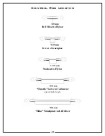
Page 44: ...44 Control Rod Lengths Bell Mixer to Flybar Servo to Swashplate Washout to Flybar Throttle Servo to Carburetor approximate length Hiller Swashplate to Bell Mixer...

Page 45: ...ctly in the middle of its travel Failing to get them set at center will create interaction in your swash plate travel If possible center the horns on the servos without using any sub trim As a last re...

Page 46: ...he swashplate should tilt to the right and left it doesn t matter if it moves right when you push the stick left we ll fix that later Also when you move the right stick forwards and aft the elevator s...

Page 47: ...avel and take a reading of the pitch gauge and remember that number It should be a positive pitch value and 10 degrees is a good place to start Now place the collective stick at the full bottom of it...

Page 48: ...open you can decrease the endpoint but ideally you want the endpoints as close to 100 and 100 as possible If you are experiencing the need for more servo movement try moving the ball link out one hol...

Page 49: ...ontrol Ball MA0133 Ball Link for 2mm MA0133 1 Grey Ball Link for 3mm MA0159 M3 x 7 x 3 Ball Bearing MA0183 M10 x 19 x 5 Ball Bearing MA0208 10mm Torrington Clutch Bearing MA0214 Upper Swashplate Ring...

Page 50: ...Shaft MA128 108 Start Shaft Sleeve MA128 109 Start Shaft Assembly MA128 110 Clutch Bell Unit MA128 111 Clutch Bell MA128 113 Pinion Gear MA128 118 6mm Hex Starting Adaptor MA128 120 Clutch Drive Beari...

Page 51: ...51 Notes...

Page 52: ...52 Notes...

Page 53: ...53 Notes...

Page 54: ...54 Notes...

Page 55: ...d crash damaged or altered by unauthorized agencies is not covered Under no circumstances will the buyer be entitled to consequential or incidental damages The components used in this kit are made fro...

Page 56: ...2885 Farley Lane Billings MT 59101 USA Phone 1 406 245 4883 Website http www miniatureaircraftusa com Email minair miniatureacraftusa com...

Reviews: