USER GUIDE
6
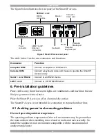
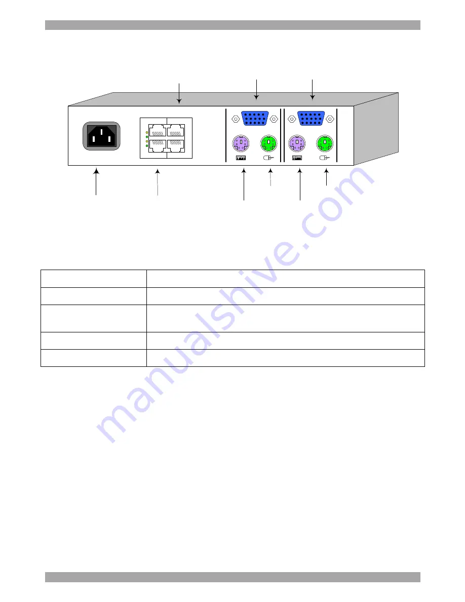
The figure below illustrates the rear panel of the Smart IP Access.
Figure 2 Smart IP Access rear panel
The table below lists the rear connectors and functions.
Connector
Function
Computer KVM
Connect a computer or KVM switch
Console KVM
Connect a keyboard, video and mouse to operate the Smart IP
Access locally
Serial 1
and
2 RS232
Connect to an RS232 device
LAN 1
and
2
Connect to 10/100 Mbit Ethernet
6. Pre-installation guidelines
Place cables away from fluorescent lights, air conditioners, and machines that are
likely to generate electrical noise.
Place the Smart IP Access on a flat, clean and dry surface.
The Smart IP Access is not intended for connection to exposed outdoor lines
6.1 Avoiding general rack mounting problems
Elevated operating ambient temperature
The operating ambient temperature of the rack environment may be greater than
the room ambient when installing into a closed or multi-unit rack assembly. So
install the equipment in an environment compatible with the maximum rated
ambient temperature.
Power
connector
Keyboard
Mouse
Monitor
Computer
Keyboard port
Computer
Mouse port
Computer
Video card
LAN 1
and
2
Ethernet
connectors
SERIAL 1
and
2
RS232
connectors
POWER
100-240 VAC 50/60 Hz
www.minicom.com
CONSOLE
COMPUTER
2
2
1
1
L
A
N
S
E
R
I
A
L


