background image

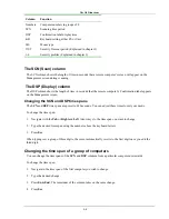
The OSD functions 


2-1 

Chapter 2: The OSD functions 

The Phantom system is controlled and monitored through an On-Screen-Display (OSD) on the Manager screen. 
When the Phantom Manager is the UPM you can also use Minicom’s Control software or equivalent software. 
The Control software is discussed in chapter 4. The OSD contains a number of different windows that are 
accessed using Hot-keys. Each window has its own special function. 

Displaying the OSD 

To display the OSD:  

Press 

Shift

Shift

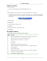
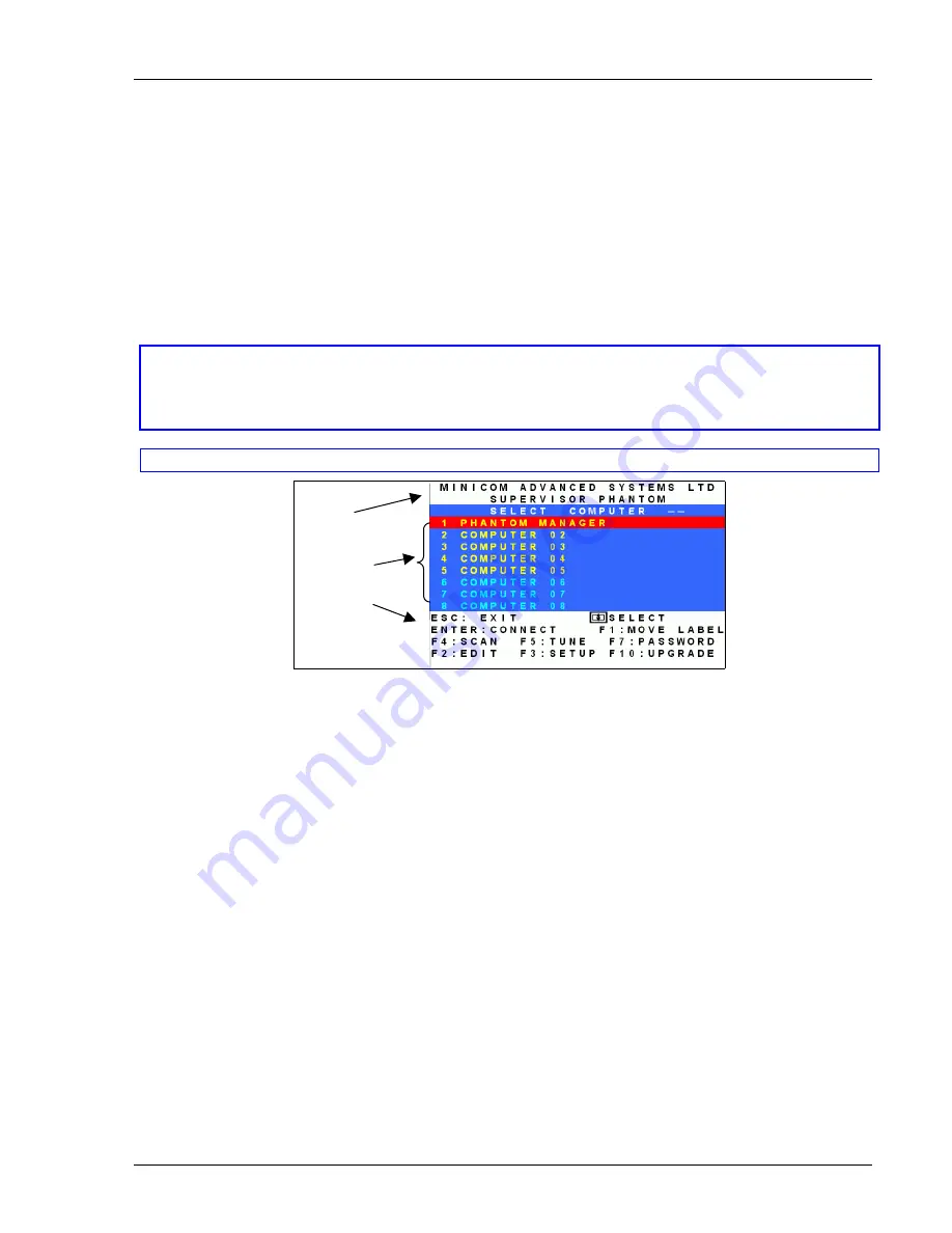
. The Select Computer window


appears. See Figure 2-1.  

Pressing keyboard hotkeys 

Note! For all keyboard hotkey sequences mentioned in this guide – press the first key, release and then 
press the next key. 

Note! When using a UPM not connected to a local computer the OSD appears automatically. 

Instructions 
and 
Hot-keys 

Computers 

Name 


Figure 2-1 The Select Computer window 

The OSD is divided into three sections. These are: 

• 

Name 

• 

Computers 

• 

Instructions and Hot-key guide 

The Computers section 

The Computers section displays the computers in groups of eight.  

Navigate between the groups with the 

Page


Up


and 

Page Down


Arrow keys. 

In this section you select computers - discussed below. 

Line Color codes 

Each computer line can be one of three colors as follows:  

Yellow 

Connected and switched on computer. 

Black 

Connected and switched on computer with a Local Workstation attached and presently being 
used locally. After remaining idle for 30 seconds, it changes to 

yellow

.


Blue 

Unconnected or switched off computer. 

Summary of Contents for Minicom Supervisor Phantom

Page 1: ...rican HQ Linden New Jersey Tel 1 908 4862100 info usa minicom com German Europe Zurich Switzerland Tel 41 1 455 6220 info german minicom com Italy Rome Tel 39 06 8209 7902 info italy minicom com www m...

Page 2: ...y be either internal PCI cards or Micro sized external boxes called Specters There are a number of Specter types as follows For PS 2 interface computers Specter PS 2 for 1 User system Specter II PS 2...

Page 3: ...ntom configuration for the Manager and Remote PCI cards SD P1610 Remote Computer 1 OUT IN OUT IN OUT IN OUT RS232 CAT5 System Cable CAT5 System Cable CAT5 System Cable Terminator in the last Phantom U...

Page 4: ...50 60 Hz Link Active MINICOM www minicom com PHANTOM S p e c t e r OUT IN Link Active MINICOM www minicom com PHANTOM S p e c t e r OUT IN Link Active MINICOM www minicom com PHANTOM S p e c t e r OUT...

Page 5: ...tive MINICOM www minicom com PHANTOM S p e c t e r Link Active MINICOM www minicom com PHANTOM S p e c t e r Link Active MINICOM www minicom com PHANTOM S p e c t e r Link Active MINICOM www minicom c...

Page 6: ...kstation Option When using the Phantom Remote PCI cards you have the option of working at the remote computer by connecting a keyboard video and mouse to it This is called the Local Workstation option...

Page 7: ...key release and then press the next key Note When using a UPM not connected to a local computer the OSD appears automatically Instructions and Hot keys Computers Name Figure 2 1 The Select Computer w...

Page 8: ...ss Shift Esc To return to the previously accessed computer screen Press Shift Tab The hotkey functions The OSD hotkey functions are briefly outlined in the table below Hotkey Function F1 Move label id...

Page 9: ...lay the Edit Mode window Press F2 The Edit Mode window with instructions appears see Figure 2 3 Instructions Computers Name Figure 2 3 The Edit Mode window Navigating between sections To navigate betw...

Page 10: ...each line is unalterable You can substitute the text that appears after the number with up to 20 characters per line Editing a group of lines You can edit a group of lines with the same data change To...

Page 11: ...hanging the SCN and DSP time spans The SCN and DSP time spans are preset to 030 seconds You can adjust these times to suit your needs To change the time span 1 Navigate with the Tab or Right and Left...

Page 12: ...according to its operating system The default KB mode is PS which is the standard keyboard mapping for Windows and Linux based operating systems For a UNIX operating system using a standard PS 2 keybo...

Page 13: ...y remote computer screen from the Select Computer window To adjust the screen image 1 Navigate to the remote computer you wish to adjust 2 Press F5 The screen image of the selected computer appears to...

Page 14: ...ress F8 until you reach the desired language 2 Press Esc Changing the OSD display hotkey F9 The default hotkey to display the OSD is Shift Shift You can replace this hotkey with any of the following F...

Page 15: ...following OSD functions only F1 Moving the Confirmation label F4 Scan and F5 Tune User Status U Lowest There are 6 different Users in the Phantom system Each User has a Profile that defines the acces...

Page 16: ...igure 3 2 The Password window 4 Press F7 The Confirmation label appears The password indication in the hotkey section of the OSD changes to PASSWORD ON 5 Press Y to confirm Password protection is now...

Page 17: ...isor name and password Note Password characters are not case sensitive and a space can be a password character A space will appear as an asterix To set up a password 1 Navigate to the desired line num...

Page 18: ...with their password they see the access levels for each computer displayed on the OSD See Figure 3 5 Figure 3 5 User access levels Accessing the OSD using a password Once password protection is enabl...

Page 19: ...nds maximum 998 seconds For the rest of the column downwards to take on the same change press End End 4 Press Esc When Timeout is activates the keyboard and mouse are disabled and the monitor blacks o...

Page 20: ...Press F7 The Enter Password box appears See Figure 3 8 Figure 3 8 The Enter Password box 2 Type the Administrators password default password is ADMIN and press Enter The Password window appears Figur...

Page 21: ...ware requires 2 monitors 1 for the software and 1 to view the computer screens With the Control software you can View computers Edit server properties Save configurations for future use Read configura...

Page 22: ...alling and running the Control software Note The Phantom system must be fully connected BEFORE running the Control software Failure to first connect the system will lead to the software working in dem...

Page 23: ...is complete the Control window appears See the figure below Figure 4 2 The Control window Computer icons Icon Meaning Remote computer is connected and switched on Remote computer is switched off or un...

Page 24: ...ons Com Port are set correctly After changing the Com port exit and re enter the Control software The View menu From the View menu choose to display All computers or only active switched on computers...

Page 25: ...With the Control software you can make changes to all OSD settings You can then save these configurations in a file to use in the future by selecting Save or Save As from the File menu Note Save or S...

Page 26: ...ke the desired changes 3 Click OK Settings Choose Settings from the Edit menu The Computers Properties box appears See Figure 4 6 Figure 4 6 The Settings box Here you can edit all the data that can be...

Page 27: ...e with the Control software are only reflected in the OSD AFTER pressing Password protection When the Phantom system is password protected the Control software behaves in exactly the same way as the O...

Page 28: ...puters There are 3 different access levels These are Y Full access to a particular computer V Viewing access only to a particular computer No keyboard mouse functionality N No access to a particular c...

Page 29: ...ter containing the software and to the Phantom Manager See chapter 5 of the Installation guide RS232 Serial cable system requirements Pentium 166 or higher computer 16Mb RAM Windows 98 NT4 SP6 2000 ME...

Page 30: ...ot be altered with the Phantom Numbering software Failure to number Scanning the system In the toolbar click Scan This maps out the computers connected to the system When finished the window appears a...

Page 31: ...ates When finished the ID numbers are assigned according to the physical position of the units Manual numbering Manual numbering involves selecting an ID number box and assigning a number from the Dro...

Page 32: ...ng the Auto Default or Manual numbering but BEFORE clicking Apply you can revert to the position as it was before the changes To do so Click Cancel Restore After making changes to ID numbers using the...

Page 33: ...Renumbering the Phantom Remotes 5 5 Fail icons When after a carrying out a numbering procedure Fail icons appear see Figure 5 7 Wait 30 seconds and repeat the numbering procedure Figure 5 7 Fail icons...

Page 34: ...hantom Update software Pentium 100 or higher with 8 MB RAM and 4 MB free Hard Drive space Free Serial port Windows 95 98 2000 ME XP or Windows NT 4 0 SP service pack 3 or later Connecting the Phantom...

Page 35: ...hantom Update window Button or Box Function Selects all remote computers Unselects selected remote computers Starts firmware download Displays the firmware version number Displays the hardware version...

Page 36: ...rade mode on the Phantom Manager OSD To activate the Firmware Upgrade mode 1 Display the Manager OSD window The default Display hotkey is Shift Shift 2 Press F10 The Firmware Upgrade mode activates Th...

Page 37: ...rdware version number appears in the Manager Unit box Verifying the Remote version number Before you can check a remote computer you must uncheck the Manager Unit box options To verify the Remote vers...

Page 38: ...ee Figure 6 6 5 Navigate to the folder that contains the firmware update file You may only see the files that match the file selection mask Figure 6 6 The Mask for a Remote computer 6 Open the file 7...

Page 39: ...e Serial port and avoids the need to shut down the computer NOTE The Reset function does not affect the parameters of the unit settings Resetting the Manager or Remote units To reset the Manager or Re...

Page 40: ...omatically without displaying the Firmware Upgrade label Simply resume the firmware update by opening the folder that contains the firmware update file and continue from there If the electricity fails...

Page 41: ...ombo keys See the table below SUN key Combo key Stop Left Ctrl Alt F1 Props Left Ctrl Alt F3 Front Left Ctrl Alt F5 Open Left Ctrl Alt F7 Find Left Ctrl Alt F9 Again Left Ctrl Alt F2 Undo Left Ctrl Al...

Reviews: