miniDSP Ltd – Hong Kong /
www.minidsp.com
/ Features and specifications subject to change without prior notice
18
4.2
C
ONNECTIONS FOR ACOUSTIC MEASUREMENT
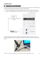
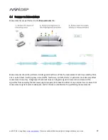
The figure below shows a typical connection diagram for performing acoustic measurement. (This example uses
the DDRC-22D.) No changes to existing audio connections are needed. Simply:
1.
Connect the supplied USB (type A to type B) cable from the processor to a USB port on the computer.
2.
Connect the supplied USB (type A to mini type B) cable from the UMIK-1 to a USB port on the computer.
Place the UMIK-1 microphone into the microphone stand and point it between the speakers. Position the
computer and cabling so that there is enough freedom of movement to move the microphone into the needed
locations.


