background image


miniDSP Ltd – Hong Kong / 

www.minidsp.com

 / Features and specifications subject to change without prior notice


T

ABLE OF 

C

ONTENTS


Important Information ......................................................................................................................................... 5 

System Requirements ...................................................................................................................................... 5 
Disclaimer/Warning ......................................................................................................................................... 5 
Warranty Terms ............................................................................................................................................... 5 
Package Contents ............................................................................................................................................ 6 
A Note on this Manual ..................................................................................................................................... 6 

1  Product Overview .......................................................................................................................................... 7 

1.1 

Typical system configurations ............................................................................................................... 7 

1.2 

How Dirac Live® works ......................................................................................................................... 9 

1.3 

Dirac Series / Dirac Live® configuration steps ...................................................................................... 10 

2  Hardware Connectivity ................................................................................................................................ 11 

2.1 

Audio input and output connections................................................................................................... 11 

2.2 

DC Power ........................................................................................................................................... 13 

2.3 

USB .................................................................................................................................................... 13 

3  Software Installation ................................................................................................................................... 14 

3.1 

A note on Dirac Live license activation ................................................................................................ 14 

3.2 

Installation ― Windows...................................................................................................................... 15 

3.2.1 

Possible Windows installation issues ........................................................................................... 15 

3.2.2 

DDRC-22 Utility installation ......................................................................................................... 15 

3.2.3 

DLCT installation ......................................................................................................................... 15 

3.3 

Installation ― Mac OS X ..................................................................................................................... 16 

3.3.1 

Possible Mac installation issues .................................................................................................. 16 

3.3.2 

DDRC-22 Utility installation ......................................................................................................... 16 

3.3.3 

DLCT installation ......................................................................................................................... 16 

4  Acoustic Measurement ................................................................................................................................ 17 

4.1 

Loudspeaker and microphone positioning .......................................................................................... 17 

4.2 

Connections for acoustic measurement .............................................................................................. 18 

4.3 

Configuring for measurement ............................................................................................................. 19 

4.3.1 

Sound System tab ....................................................................................................................... 20 

4.3.2 

Mic Config tab ............................................................................................................................ 20 

4.3.3 

Output & Levels tab .................................................................................................................... 21 

4.4 

Running the measurements ................................................................................................................ 22 

4.4.1 

Listening environment ................................................................................................................ 23 

4.4.2 

Executing measurements ............................................................................................................ 24 

4.4.3 

Viewing and redoing measurements ........................................................................................... 25 

4.4.4 

Completing the measurements ................................................................................................... 25 

4.5 

Saving and loading projects ................................................................................................................ 25 

5  Filter Design ................................................................................................................................................ 26 

5.1 

Working with graphs .......................................................................................................................... 26 

5.2 

Designing your target curve ................................................................................................................ 28 

5.2.1 

The Auto Target .......................................................................................................................... 28 

Summary of Contents for DDRC-22DA

Page 1: ...d Hong Kong www minidsp com Features and specifications subject to change without prior notice 1 DIRAC SERIES HIGH RESOLUTION AUDIO PROCESSORS WITH DIRAC LIVE TECHNOLOGY DDRC 22A DDRC 22D DDRC 22DA Us...

Page 2: ...release 26 Mar 2014 1 0 First production version 4 April 2014 1 1 Added DDRC 22DA 18 May 2015 1 2 Updated firmware upgrade procedure 20 May 2015 1 3 Updated for Mac version of software 11 July 2015 1...

Page 3: ...2 1 Possible Windows installation issues 15 3 2 2 DDRC 22 Utility installation 15 3 2 3 DLCT installation 15 3 3 Installation Mac OS X 16 3 3 1 Possible Mac installation issues 16 3 3 2 DDRC 22 Utilit...

Page 4: ...ng target curves 31 5 3 Generating correction filters 31 5 4 Loading filter sets 32 6 Using the Dirac Series Audio Processor 33 6 1 Status indicators 33 6 2 Front panel controls 33 6 3 Infrared remote...

Page 5: ...se or incorrect configuration of this product Please read this manual carefully to ensure that you fully understand how to operate and use this product as incorrect use or use beyond the parameters an...

Page 6: ...n both print and on the computer If printing the manual please print double sided The embedded page size is 8 x 11 Printing on A4 paper will result in a slightly reduced size For reading on the comput...

Page 7: ...Improve the timbre Remove resonances and room modes Reduce early reflections Dirac Series processors are available in several versions The DDRC 22A has analog inputs and outputs while the DDRC 22D has...

Page 8: ...use of an integrated amplifier with a digital input or the use of a digital input of an A V receiver in which case a separate DAC is not required The DDRC 22DA digital input analog output is typically...

Page 9: ...aker The impulse response is a critical factor for accurate sound staging clarity and bass reproduction Dirac Live employs a sophisticated analysis algorithm to make the optimal correction across the...

Page 10: ...ustic measurements using the Dirac Live Calibration Tool Stereo for miniDSP program to capture the acoustic behavior of your speakers and room See Section 4 Acoustic Measurement 3 Generate digital roo...

Page 11: ...puts DDRC 22D Connect one of the digital outputs to your DAC or other device with a digital input All digital outputs are simultaneously active so multiple output connections can be made if necessary...

Page 12: ...miniDSP Ltd Hong Kong www minidsp com Features and specifications subject to change without prior notice 12 DDRC 22D connections DDRC 22A connections DDRC 22DA connections...

Page 13: ...acoustic measurements in your listening room and to generate and download the digital room correction filters to the Dirac Series processor To configure the processor connect the USB port of the proce...

Page 14: ...iguration tool This will install the DDRC 22 Utility program used to configure remote control codes and perform various other maintenance operations on the processor Download this file for both Window...

Page 15: ...t operating system or x64 64 bit operating system 3 2 2 DDRC 22 Utility installation 1 Navigate to the Windows sub folder of the unzipped utility program download 2 Double click on the DDRC_22 exe ins...

Page 16: ...mmend that you accept the default installation settings 3 To run the DDRC 22 Utility locate DDRC 22 app in the Applications miniDSP folder and double click on it To make it easier to run in future rig...

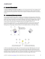
Page 17: ...er surfaces With Dirac Live you have more freedom with loudspeaker placement but the best result will still be achieved if optimal loudspeaker placement is used together with Dirac Live You should als...

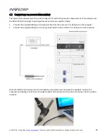
Page 18: ...changes to existing audio connections are needed Simply 1 Connect the supplied USB type A to type B cable from the processor to a USB port on the computer 2 Connect the supplied USB type A to mini typ...

Page 19: ...lculations Screen selection tabs Each tab selects a different step of the calibration process These are generally worked through in order from top to bottom This section covers the first four tabs the...

Page 20: ...set to DDRC 22 miniDSP Ltd This will ensure that test signals are sent into your audio system via the Dirac Series processor If this is not present check that your processor is connected via USB and p...

Page 21: ...t unless you are pointing the microphone at the ceiling Once you have verified that this tab is correct click the Proceed button 4 3 3 Output Levels tab On the Output Levels tab set Output volume quit...

Page 22: ...measurement technique used by Dirac Live is quite robust low frequency noise traffic machinery aircraft storms in particular can adversely affect measurement accuracy A high level of ambient noise can...

Page 23: ...ever imperative that the first measurement is taken in the center of the listening area as this measurement is used to set the levels and delays of each channel The subsequent eight measurements shoul...

Page 24: ...e bottom of the measurement tab This graph is related to the magnitude response but is not the same display Its purpose is to verify that the recorded signal level is in a suitable range At the comple...

Page 25: ...successfully measured Note that it is good practice to save the project periodically while performing measurements see Saving and loading projects Once all nine measurements have been completed you ca...

Page 26: ...umber of plots that can individually be turned on and off with the checkboxes near the top of the screen Avg spectrum before The average of the measured magnitude responses These plots are shown in li...

Page 27: ...impulse response after correction shown in light green To return to the magnitude response click on the Spectrum button The magnitude and impulse response graphs can be viewed at a larger scale To zoo...

Page 28: ...els drag the disconnected channel tab over the top of the selected channel 5 2 DESIGNING YOUR TARGET CURVE The target curve is the desired in room frequency response with the Dirac Series processor pe...

Page 29: ...rection for your system and environment For example low frequency noise traffic machinery may be present in some environments so it is best to adjust the frequency range to exclude these frequencies f...

Page 30: ...quency tilt The target curve is the desired measured response of loudspeakers in a room In contrast to measurements made of a loudspeaker during its design under anechoic measured in free space condit...

Page 31: ...the file To load a target curve click on Load Target Note that loading a target will erase the current target so be sure to save it first if needed If the channels are linked then the target curve wil...

Page 32: ...can icon Then drag and drop the current filter set onto the now empty slot The name displayed on the filter slot after dragging and dropping is the name of the project This example shows three slots l...

Page 33: ...ac Live Indicates that Dirac Live filtering is turned on 6 2 FRONT PANEL CONTROLS The Dirac Series audio processors use a minimalist physical control design with a single control knob To change the vo...

Page 34: ...earn the control codes of your current remote if it supports one of the following remote control codes NEC Sony Philips RC6 To initiate the learning process run the DDRC 22 utility and click Connect C...

Page 35: ...ity Attenuation By default the DDRC 22 introduces 10 dB of attenuation in order to provide headroom for the EQ boost that Dirac Live may introduce If this is too much attenuation you can change it wit...

Page 36: ...nnector Isolated with digital audio transformer Toslink on Optical connector Digital audio is always output at a sample rate of 96 kHz Analog Audio Inputs DDRC 22A Balanced audio inputs on XLR Neutrik...

Page 37: ...gram 3 Click on the Connect button The button will display a green tick if connection is successful 4 Click on the Upgrade Firmware button The Dirac Series processor will be put into boot loader mode...

Page 38: ...play should show Device attached 5 Click on the Import Firmware Image button and select the hex file located in the firmware folder of the download It will have a name like ENC_DDRC22_Ver2 18_SS hex 6...

Page 39: ...ce has the Dirac Series processor selected for input e Check that any downstream volume control is not set to zero f Check that no downstream device is muted or powered off 3 No input from measurement...

Page 40: ...aised and a solution or solutions provided 2 Contact miniDSP via the support portal at minidsp desk com with a The product information obtained from DDRC 22 Utility About button and Dirac Live Calibra...

Reviews: