mi niDSP Ltd, Hong Kong /
/ Features and speci fi cations subject to change wi thout pri or noti ce
20
3.3
C
ONFIGURE SIGNAL ROUTING
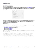
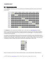
Click on
Routing
in the Selection tabs. The input channels are labeled along the left, and the output channels
along the top.
(The
LFE Mgt
row is the output from the LFE Mgt screen. For information, see
below.)
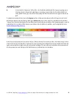
Each cross-point represents a switch that can either be turned off, or turned on with a gain setting. By default,
each input channel is switched to the corresponding output channel with 0 dB gain (i.e. no change in level), as
shown in the above screenshot.
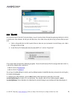
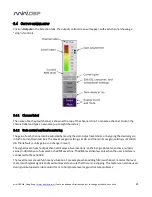
Any number of input channels can be mixed to each output channel. At each cross-point, the gain of the signal
being mixed can be adjusted to a value between -72 and +12 dB. To adjust the gain, right-click on the cross-point
and a gain control will appear. Adjust the gain with the slider, or by typing in the value directly. This screenshot
shows the gain control, with two input channels mixed to one output channel, each at -6 dB:
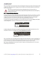
Note: To rename an input channel, click on its label and type in a new name (maximum of eight characters).

