mi niDSP Ltd, Hong Kong /
/ Features and speci fi cations subject to change wi thout pri or noti ce
21
3.4
O
UTPUT CHANNEL SETUP
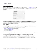
Click on
Outputs
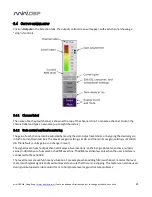
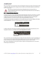
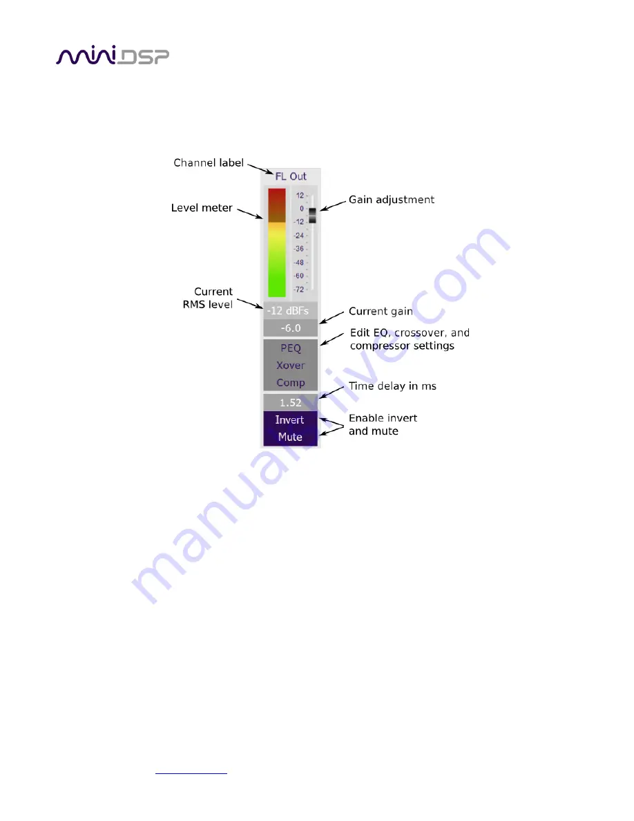
in the Selection tabs. The output control screen will appear, with each channel showing a
“strip” of controls.
3.4.1
Channel label
The name of each output channel is shown at the top of the channel strip. To rename a channel, click on the
channel label and type a new name (up to eight characters).
3.4.2
Gain control and level monitoring
The gain of each channel can be adjusted by moving the Gain Adjustment slider, or by typing the desired gain
into the Current Gain text box. The maximum gain setting is 12 dB, and the minimum gain setting is –72 dB. (0
dB, the default, is unity gain or no change in level.)
The signal level on each output channel displays in two locations: on the bar-graph meter, and as a numeric
value (in dB relative to full scale) in the RMS Level box. The RMS level displays only when the user interface is
connected to the nanoAVR.
The level meters are useful in many situations. For example, when adding filters with boost, monitor the level
meters with typical signals and maximum levels to ensure that there is no clipping. The meters can also be used
during normal operation to monitor for or to help locate level or gain structure problems.

